








 English
 Français
 Deutsch
 Português
 Español
 русский
  한국어
한국어 العربية
 Italiano
 Indonesia
 Schweiz
 Polski
 Nederlands
 ישראל - עברית
 Perzisch
 ไทย
ไทย 日本語
日本語 ኢትዮ-አማርኛ
 Việt Nam
 Kiswahili
 Srpski
 Ελληνικά
 简体中文
简体中文Industrial Control Cabinet Cooling Selection Guide: Prevent Equipment Overheating and Downtime in 3 Steps — “Power Calculation → Fan Matching → Installation Layout”
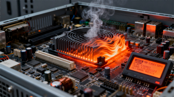
Overheating is one of the most common causes of failure in industrial control systems. According to industry statistics, approximately 40% of control equipment failures are related to poor heat dissipation — and most of these issues stem from incorrect selection or improper installation. For engineers, a scientific cooling design process should follow three core steps: heat calculation, fan matching, and layout design, to achieve effective cooling, reasonable energy use, and convenient maintenance. The following explains each step in detail with practical examples.
Step 1: Calculate the Total Heat Dissipation and Define the Cooling Baseline
The total heat dissipation of a control cabinet depends on device power loss and environmental temperature difference.
The core formula is:
Total Heat Dissipation (W) = Σ (Rated Power × Loss Coefficient) − Environmental Compensation (W)
Different devices have varying loss coefficients:
-
Control devices such as PLCs and touchscreens: 0.1–0.2 (10–20% of rated power converted to heat)
-
Power devices such as inverters and servo drives: 0.05–0.15 (add +0.03 if braking units are used)
-
Small components such as sensors and relays: 5–10W per device
Example:
A cabinet includes one inverter (1.5 kW, loss coefficient = 0.1), one PLC (200 W, loss coefficient = 0.15), and two sensors (50 W each).
Ambient temperature: 35 °C (no extra compensation).
Total heat dissipation = (1500×0.1 + 200×0.15 + 2×5) = 150 + 30 + 10 = 190 W
Based on experience, each watt of heat requires 1.2–1.5 m³/h of airflow for effective removal.
Thus, the required airflow = 228–285 m³/h, serving as the basis for fan selection.
Step 2: Select the Proper Fan Model Based on Airflow and Application Conditions
Fan selection must balance airflow, operating temperature, bearing type, and noise, avoiding both over- and under-capacity mismatches.
1. Airflow Matching
Each fan must provide enough airflow to meet total demand. If one fan is insufficient, multiple units can be installed in parallel (note: actual combined airflow is ~10% less than theoretical).
Example:
For the 190 W cabinet above, total airflow = 228–285 m³/h.
If using the ebm-papst 4650N fan (single unit airflow = 160 m³/h), one fan isn’t enough — two in parallel yield about 160×1.8 = 288 m³/h, meeting requirements.
2. Environmental Suitability
-
For high-temperature environments (e.g., steel plants, ambient > 40 °C), choose fans rated for ambient ≥ 55 °C (e.g., 4650N).
-
For low-temperature outdoor cabinets, use fans with thermal control modules to ensure reliable cold-start performance.
3. Bearing Selection
-
For 24-hour continuous operation, use sleeve bearings (such as the 4650N with Sintec bearings) for longer life and low noise.
-
For vibration-prone environments (e.g., near machining tools), use ball-bearing fans for better vibration resistance.
4. Noise Control
In work areas near operators, fan noise should not exceed 50 dB(A).
The 4650N’s 46 dB(A) sound level meets this requirement and minimizes disturbance.
Step 3: Optimize Installation Layout to Prevent Airflow Turbulence
Even with correct fan selection, improper installation can severely impair heat dissipation.
Follow these three key layout principles: smooth airflow, no dead zones, no short circuits.
1. Airflow Direction
Adopt the “bottom-in, top-out” layout — intake fans at the cabinet bottom and exhaust fans at the top. This leverages the natural rise of warm air for efficient circulation.
For instance, the 4650N’s “frame-side intake” configuration makes it ideal as a bottom intake fan. Leave at least 10 cm clearance on the intake side to prevent obstruction by cables or equipment.
2. Prevent Airflow Short-Circuiting
Ensure intake fans draw cool ambient air, and exhaust fans expel hot air outside the cabinet. Avoid placing intake and exhaust fans too close, which could cause recirculation of hot air.
3. Eliminate Hot Spots
In areas of high power density (e.g., inverter layer), install additional fans or deflectors to guide airflow through that zone first.
For sealed modules, add ventilation holes to the enclosure to prevent internal heat buildup.
Case Example:
An automotive parts workshop experienced frequent inverter shutdowns due to overheating.
After recalculating total heat dissipation (220 W) and installing two 4650N fans in parallel (total airflow 288 m³/h), with a layout of two intakes at the bottom and one exhaust at the top, plus a deflector near the inverter, the results were dramatic:
-
Internal cabinet temperature dropped from 68 °C → 48 °C
-
Inverter shutdowns fell from 8 times/month → 0
This validated the effectiveness of the “calculation → matching → layout” approach.
Conclusion
Cooling design for industrial control cabinets isn’t about simply “choosing the largest fan.”
Instead, engineers must consider actual heat generation, environmental conditions, and installation constraints.
By following the scientific three-step process — calculation, matching, and layout optimization — you can ensure long-term cooling stability and reliable operation of industrial control systems.