







 English
 Français
 Deutsch
 Português
 Español
 русский
  한국어
한국어 العربية
 Italiano
 Indonesia
 Schweiz
 Polski
 Nederlands
 ישראל - עברית
 Perzisch
 ไทย
ไทย 日本語
日本語 ኢትዮ-አማርኛ
 Việt Nam
 Kiswahili
 Srpski
 Ελληνικά
 简体中文
简体中文Motor Protection Circuit Breaker: From Technical Principles to Selection and Maintenance
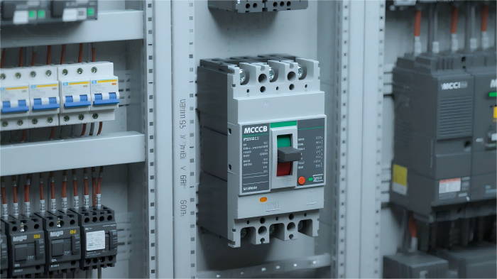
In industrial production scenarios, motors serve as core power sources, and their stable operation directly determines the efficiency and safety of production lines. However, faults such as overload, short circuit, phase loss, and locked rotor often lead to motor burnout, which not only causes equipment damage but also may trigger production shutdowns. According to the China Industrial Equipment Fault Statistics Report, approximately 68% of motor faults stem from electrical circuit anomalies. As the "first line of defense," Motor Protection Circuit Breakers (MPCBs) can minimize fault losses through accurate monitoring and rapid circuit interruption. This article provides a comprehensive analysis of MPCBs, covering technical principles, selection methods, installation and maintenance, as well as industry trends, to offer systematic solutions for industrial users.
I. Understanding Motor Protection Circuit Breakers: More Than "Power Cut-Off," It’s "Intelligent Protection"
1.1 Definition and Core Functions: "Dedicated Protection" Distinguishing It from Ordinary Circuit Breakers
A Motor Protection Circuit Breaker (MPCB) is an overload and short-circuit protection device specifically designed for motors, integrating dual functions of "circuit interruption" and "motor operating condition monitoring." Its core differences from ordinary circuit breakers are as follows:
- Protection Characteristics Adapted to Motor Starting Curves: The current during motor startup can reach 5-8 times the rated current (starting inrush current), which easily triggers false protection in ordinary circuit breakers. MPCBs utilize an "inverse time-delay protection characteristic" to allow short-term high currents to pass, avoiding false tripping during startup.
- Multi-Dimensional Fault Monitoring: In addition to basic overload and short-circuit protection, high-end MPCBs can also monitor motor-specific faults such as phase loss, locked rotor, and ground faults, covering over 90% of motor failure scenarios.
- Resettability and Adjustability: Overload protection can be manually reset without replacing components; the protective current value can be flexibly adjusted according to the motor’s rated current to adapt to motors of different powers (e.g., 1.5kW, 5.5kW, and 11kW motors can share the same MPCB model with only parameter adjustments).
1.2 Technical Principles: Three Core Mechanisms for Accurate Protection
The protection function of MPCBs relies on the coordinated operation of "bimetallic strip overload protection" and "electromagnetic short-circuit protection," with some high-end models incorporating electronic monitoring modules to form a three-layer protection system:
- Overload Protection (Inverse Time-Delay Characteristic): The core component is a bimetallic strip (composed of two metals with different thermal expansion coefficients). When the motor is overloaded, current passes through the bimetallic strip to generate heat. Due to the difference in thermal expansion, the strip bends and pushes the tripping mechanism to interrupt the circuit. The greater the overload current, the faster the bimetallic strip bends, and the shorter the tripping time (e.g., at 1.2 times the rated current, the tripping time is approximately 20 minutes; at 6 times the rated current, the tripping time is only 0.1 seconds). This perfectly matches the "current-time" characteristic of motor overload faults.
- Short-Circuit Protection (Instantaneous Characteristic): It relies on an electromagnetic release. When a short circuit occurs in the circuit (current can reach 10-20 times the rated current), the electromagnetic coil generates a strong magnetic field, attracting the armature to strike the tripping mechanism and instantly interrupt the circuit (tripping time ≤ 0.02 seconds), preventing the short-circuit current from burning the motor windings and cables.
- Electronic Auxiliary Protection (High-End Models): Current sensors collect three-phase current in real time, and a chip analyzes the motor’s operating conditions. If the current in one phase is 0 (phase loss) or suddenly increases to more than 3 times the rated value (locked rotor), electronic tripping is triggered immediately. Its response speed is 50% faster than mechanical protection, making it suitable for precision motors (e.g., servo motors, stepper motors).
Figure 1: Schematic Diagram of the Three-Layer Protection Mechanism of a Motor Protection Circuit Breaker (Overload Protection - Bimetallic Strip, Short-Circuit Protection - Electromagnetic Release, Electronic Protection - Current Sensor)
II. Selection Guide: Avoid 90% of Selection Errors by Focusing on These 4 Key Dimensions
Industrial users often experience protection failure or cost waste due to "only focusing on current parameters" or "blindly pursuing high-end models" during selection. Correct selection requires considering three factors: motor parameters, application scenarios, and protection requirements, with a focus on the following 4 core dimensions:
2.1 Step 1: Match the Motor’s Rated Current and Protection Range
The "rated current adjustment range" of an MPCB must cover the motor’s "rated operating current (Ie)" and reserve space for starting current. The selection formula is:
Upper Limit of MPCB Rated Current Adjustment ≥ Motor Rated Current (Ie) × 1.2
(The 1.2x coefficient reserves space for current fluctuations during motor startup.)
- Example: For a 5.5kW three-phase asynchronous motor with a rated current of 10A, an MPCB with an adjustment range of 6-10A or 8-12A should be selected, rather than a fixed 10A model (to avoid false tripping during startup).
- Note: Differences in selection between single-phase and three-phase motors — single-phase motors have larger startup current fluctuations, so dedicated single-phase MPCBs with "higher startup current tolerance" should be chosen (e.g., Schneider GV2 series single-phase models).
2.2 Step 2: Select the Protection Level Based on Application Scenarios
Motors face different fault risks in different industrial scenarios, requiring MPCBs with corresponding protection functions:
2.3 Step 3: Confirm Interrupting Capacity and Installation Method
- Interrupting Capacity (Icu): Refers to the maximum short-circuit current that an MPCB can safely interrupt, which must be greater than the "prospective short-circuit current" of the circuit. If the short-circuit current of the factory power distribution system is 50kA, an MPCB with an interrupting capacity ≥ 50kA should be selected (e.g., the Schneider GV3 series has an interrupting capacity of up to 100kA) to prevent the circuit breaker from exploding during a short circuit.
- Installation Method: Choose "fixed mounting" or "plug-in mounting" based on the distribution cabinet space: Fixed mounting is stable and suitable for long-term stationary scenarios; plug-in mounting supports quick insertion and removal, facilitating later maintenance (e.g., when motors are frequently replaced in production lines, the MPCB can be directly pulled out for maintenance without disconnecting wires).
2.4 Step 4: Avoid Common Selection Misconceptions
- Misconception 1: "Power matching is sufficient; no need to check current" — For motors of the same power, the rated current varies with voltage (e.g., a 5.5kW motor at 380V has a current of approximately 11A, while at 220V it is approximately 25A). Selection must be based on the actual current.
- Misconception 2: "More protection functions mean better" — Ordinary fans and water pumps do not require high-end models with ground fault protection, as excessive functions will increase costs by more than 30%; conversely, using basic MPCBs for precision equipment may lead to motor burnout due to the lack of phase loss protection.
III. Installation and Maintenance: Details Determine Protection Effectiveness — 3 Key Operations Cannot Be Ignored
Even with correct selection, MPCBs may fail if installation is non-standard or maintenance is inadequate. The following are practical key points verified in industrial scenarios:
3.1 Installation Specifications: Avoid "Hidden Faults"
- Secure Wiring: The incoming and outgoing terminals of the MPCB must be tightened with a torque wrench according to the torque specified in the manual (e.g., 8-10N・m for 10mm² copper wires). Looseness will cause terminal heating, burn the insulation layer, and trigger false tripping.
- Phase Alignment: When wiring a three-phase motor, ensure the three-phase input terminals of the MPCB correspond one-to-one with the motor’s three-phase windings (L1→U, L2→V, L3→W). Reverse connection will cause the motor to reverse, and if the motor reverses under load, it may trigger locked rotor protection.
- Heat Dissipation Space: Reserve ≥ 50mm of heat dissipation space around the MPCB, and avoid installing it in close contact with heat-generating components such as contactors and frequency converters (for every 10℃ increase in ambient temperature, the overload protection current of the MPCB decreases by 5%-8%, easily causing false triggering).
|
Application Scenario
|
Core Fault Risk
|
Recommended MPCB Protection Level
|
Typical Model Example
|
|
Ordinary conveyors, fans
|
Overload, short circuit
|
Basic type (Overload + Short-Circuit Protection)
|
Siemens 3RV1011 Series
|
|
Water pumps, compressors
|
Phase loss, locked rotor
|
Advanced type (Overload + Short-Circuit + Phase Loss Protection)
|
ABB MS116 Series
|
|
Servo motors, precision machine tools
|
Ground fault, overvoltage
|
High-end type (Full-Function + Electronic Monitoring)
|
Schneider GV3-ME Series
|
|
Explosion-proof workshops, chemical scenarios
|
Explosion-proof requirement
|
Explosion-proof type (Ex d IIB T4Gb Certification)
|
Delixi CDM3L-Ex Series
|
Figure 2: Schematic Diagram of Correct Wiring for Motor Protection Circuit Breaker, Motor, and Contactor (Including Phase Alignment and Heat Dissipation Space Markings)
3.2 Daily Maintenance: 3 Regular Inspections
- Monthly Parameter Calibration: Use a clamp ammeter to measure the motor’s operating current, and confirm that the MPCB’s protective current setting matches the actual current (e.g., if the actual current is 8A, the MPCB setting should be adjusted to 8-9.6A) to prevent protection failure due to parameter drift.
- Quarterly Mechanical Inspection: Manually operate the MPCB’s "opening/closing" buttons to check if the mechanism is flexible. If button jamming is found, disassemble and clean the internal spring (dust accumulation will cause delayed response of the tripping mechanism).
- Annual Comprehensive Testing: Use a relay protection tester to simulate overload and short-circuit faults, and check if the MPCB’s tripping time meets standards (e.g., at 1.5 times the rated current, the tripping time should be 5-10 minutes). If the tripping time deviation exceeds 20%, replace the MPCB.
3.3 Fault Troubleshooting: Deduce the Root Cause from "Tripping"
When an MPCB trips, it cannot be reset directly; the fault cause must be identified first. Common scenarios and solutions are as follows:
- Scenario 1: Immediate tripping during startup — Check if the MPCB’s current setting is too low (e.g., the motor’s rated current is 10A, but the setting is only 8A) or if the motor windings are short-circuited (use a multimeter to measure the winding insulation resistance, which should be ≥ 0.5MΩ under normal conditions).
- Scenario 2: Tripping during operation, with successful reset and restart — This is mostly an overload fault. Check if the motor load is too high (e.g., conveyor jamming) or if poor ventilation causes motor overheating (use an infrared thermometer to measure the motor housing temperature, which should be ≤ 80℃ under normal conditions).
- Scenario 3: Failure to reset after tripping — This may be due to deformation of the internal bimetallic strip (caused by overload) or damage to the electromagnetic release (caused by short circuit). Replace the MPCB with a new one.
IV. Industry Trends: Intelligence and Integration Become Mainstream; Future MPCBs Will Achieve "Predictive Protection"
With the advancement of Industry 4.0 and smart manufacturing, motor protection circuit breakers are evolving from "passive protection" to "active monitoring." The following three trends deserve attention:
4.1 Intelligence: Integration into the Industrial Internet of Things (IIoT)
High-end MPCBs are now equipped with RS485/Modbus communication interfaces, enabling them to upload data such as current, temperature, and tripping records to industrial cloud platforms (e.g., Schneider EcoStruxure, Siemens MindSphere). Users can remotely monitor via mobile phones or computers:
- Real-time viewing of motor operating current curves to predict overload risks (e.g., sending an early warning when the current continuously rises to 1.1 times the rated value);
- Automatic recording of tripping causes (e.g., "Phase loss fault tripping at 14:30 on May 20, 2024"), eliminating the need for on-site troubleshooting and improving fault localization efficiency by 80%;
- Remote reset function: If a false trip is confirmed (e.g., caused by grid voltage fluctuations), the MPCB can be remotely closed to reduce production downtime.
4.2 Integration: In-Depth Integration with Control Systems
Traditional MPCBs need to be used in conjunction with contactors and thermal relays, resulting in complex wiring and large space occupation. The new generation of "Motor Control and Protection Units (MCPs)" integrates MPCBs, contactors, and soft starters into one unit, such as the ABB M102 series:
- Volume reduced by 50%, saving distribution cabinet space;
- Built-in logic control functions to realize "star-delta starting" and "forward-reverse control" of motors without additional PLC programming;
- Linkage between protection parameters and control parameters (e.g., automatically relaxing the overload protection threshold during startup and restoring it to normal after startup), adapting to complex startup scenarios.
4.3 Green Development: Low-Power Consumption and Long-Lifespan Design
With the advancement of the "dual carbon" policy, MPCBs are adopting environmentally friendly materials and low-power technologies:
- Contacts use silver-nickel alloy, extending the service life to over 100,000 operations (traditional copper contacts have a service life of approximately 30,000 operations), reducing replacement frequency;
- Electronic components use low-power chips, reducing standby power consumption to ≤ 1W (traditional models consume approximately 5W), decreasing annual power consumption by 80%;
- The proportion of recyclable materials is increased to over 90%, complying with the EU RoHS environmental standards.
V. Conclusion: Emphasize Both Selection and Maintenance to Make MPCBs Truly "Safety Guards" for Motors
Motor protection circuit breakers are not simple accessories that "can be selected once and forgotten," but rather the "safety core" of industrial power systems. The correct approach is:
- Selection Stage: Consider motor parameters (current, voltage, power), application scenarios (load type, environmental conditions), and protection requirements (basic/advanced/high-end) to avoid "over-selection" or "missing functions";
- Installation Stage: Strictly follow wiring specifications, reserve heat dissipation space, and ensure correct phase alignment;
- Maintenance Stage: Regularly calibrate parameters, inspect mechanical performance, and use intelligent tools to achieve active monitoring;
- Upgrade Stage: Gradually replace traditional MPCBs with IoT-enabled models according to the factory’s intelligent development progress, improving the reliability and manageability of the overall power system.