






 English
 Français
 Deutsch
 Português
 Español
 русский
  한국어
한국어 العربية
 Italiano
 Indonesia
 Schweiz
 Polski
 Nederlands
 ישראל - עברית
 Perzisch
 ไทย
ไทย 日本語
日本語 ኢትዮ-አማርኛ
 Việt Nam
 Kiswahili
 Srpski
 Ελληνικά
 简体中文
简体中文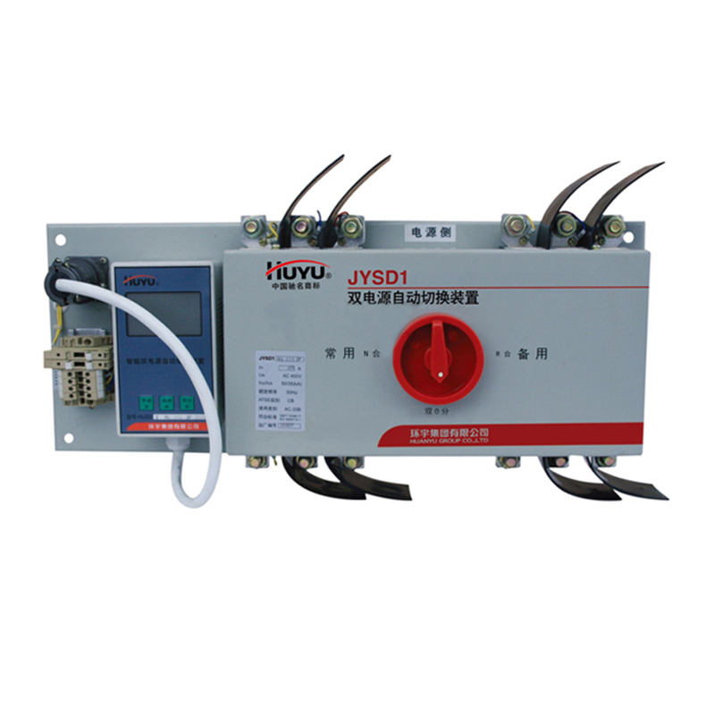
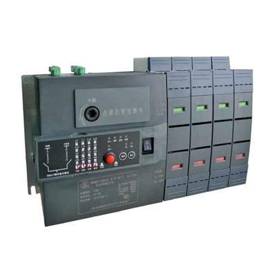
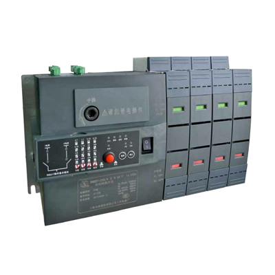
Huyu JYSD1SA-400/4P 250A Dual Power Supply
Brand:
Series:
JYSD1
Controller Type:
Intelligent
Power Supply Type:
Grid-Grid
Transfer Switch Type:
CB
Control Mode:
automatic
Operation Mode:
Self-destruction without self-recovery
Control Voltage:
-
Rated Current:
250A
Poles:
4P
Rated Voltage:
400VAC
Breaking Capacity:
35KA
Model:
JYSD1SA-400/4P 250A
Order Number:
1032200039
Description:
Automatically switched but not automatically restored, transfer switch CB level, breaking capacity 35KA, number of poles 4P, rated voltage 400VAC
Product parameters
| Product attributes | Attribute value | Filter product attributes |
|---|---|---|
| Brand: | Huyu | |
| Series: | JYSD1 | |
| Controller Type: | Intelligent | |
| Power Supply Type: | Grid-Grid | |
| Transfer Switch Type: | CB | |
| Control Mode: | automatic | |
| Operation Mode: | Self-destruction without self-recovery | |
| Control Voltage: | - | |
| Rated Current: | 250A | |
| Poles: | 4P | |
| Rated Voltage: | 400VAC | |
| Breaking Capacity: | 35KA |
Products with the same attribute : 0
Show details
Series Overview
JYSD1 series dual - power automatic transfer device
Product Information
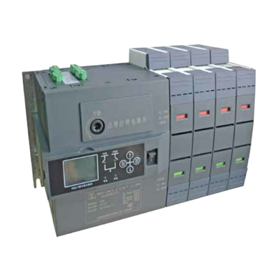
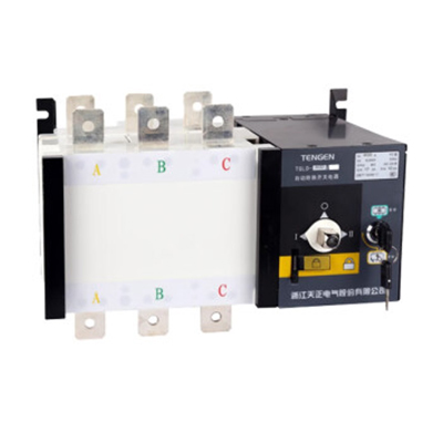
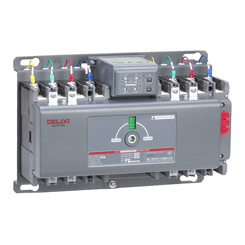
- The JYSD1 series dual - power automatic transfer device (hereinafter referred to as the transfer device) takes the single - chip microcomputer control system as the core, has strong anti - interference ability, and works stably and reliably. It is equipped with a large - screen LCD display, providing users with a good man - machine interface. It is easy to operate and highly intelligent, and is an ideal electromechanical integrated product.
Purpose and Scope of Application
- This transfer device is suitable for dual - power supply systems with an AC frequency of 50Hz, a rated voltage of single - phase 230V, three - phase or three - phase four - wire 400V, and a rated current of up to 630A. It can be used in unmanned distribution boxes and can realize the automatic transfer of two - way power supplies; when one power supply fails, it can automatically transfer to the other power supply within several seconds to ensure the timely power supply of important places (residences, hospitals, shopping malls, etc.).
- This transfer device complies with GB 14048.11 - 2016 《Low - voltage switchgear and controlgear Part 6 - 1: Multifunctional electrical equipment Transfer switch electrical appliances》.
Normal Working Conditions
- The ambient air temperature is not higher than + 40°C and not lower than - 5°C.
- The altitude of the installation site does not exceed 2000m.
- The relative humidity of the air does not exceed 50% at the maximum temperature of + 40°C; a higher relative humidity is allowed at lower temperatures. The monthly average temperature of the wettest month does not exceed + 25°C, and the monthly average maximum relative humidity of that month does not exceed 90%.
- Pollution level: 3. There is no explosive danger in the ambient air, and no gas and conductive dust that corrode metals and damage insulation.
- Installation category: III.
- The two power supply wires are connected to the upper end of the transfer device, and the load wires are connected to the lower end; reverse connection is not allowed.
- There should be no significant vibration or impact at the installation site (acceleration not greater than 5g).
Structural Features
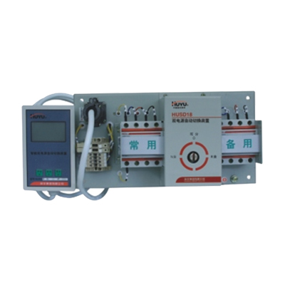
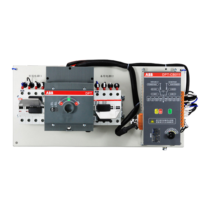
- The transfer device is composed of two major parts: the device body and the controller: The device body is composed of two circuit breakers with electric mechanisms, accessories (auxiliary, alarm contacts, etc.), mechanical interlocking mechanisms, fuses, terminal blocks, etc., installed on a metal base plate; The controller is composed of single - chip microcomputer and other electronic circuits, installed in a plastic box. The panel of the plastic box is equipped with an LCD display screen and operation buttons. The device body and the controller are connected through a dedicated aviation plug and cable to realize the automatic transfer function.
Functions
-
According to the voltage values of the two - way power supplies, control the automatic transfer of the two circuit breakers.The controller detects the phase voltages of the two - way power supplies. When the voltage has faults such as undervoltage, overvoltage, or phase failure, the circuit judges and processes the detection results. After the set delay, the controller sends instructions to the electric mechanisms to make the two circuit breakers transfer.
-
Liquid crystal display function: Chinese large - screen display.
-
Setting function: Users can set the delay for the transfer of the two - way power supplies as needed, which can be selected within the range of (1 ~ 30) s. The control function can be selected between the self - reset type and the non - self - reset type after power failure.
-
The two circuit breakers have electrical and mechanical interlocking functions to ensure that they cannot be closed at the same time.
-
Alarm functiona. When one power supply is abnormal and the two circuit breakers are transferring, the controller will emit an alarm sound. After the transfer is completed, the alarm sound stops.b. During normal operation, if the circuit breaker on the left side of the device body (code Q1) or the circuit breaker on the right side (code Q2) trips due to overload or short - circuit, the controller OA flashes, displays the "alarm" character and emits an alarm sound. Press the "double - division" key of the controller, the alarm sound stops, and the tripped circuit breaker can be reclosed.
-
Three automatic control functions: R, S, and F types.a. Functions of R - type transfer device
| Common Power Supply | Standby Power Supply | Automatic Control Function |
|---|---|---|
| Normal | Normal | Q1 closed, Q2 open, powered by common power supply |
| Abnormal | Normal | After the set N→R delay, Q1 open, Q2 closed, powered by standby power supply |
| Restored to Normal | Normal | After the set R→N delay, Q2 open, Q1 closed, restored to common power supply |
b. Functions of S - type transfer device
| Common Power Supply | Standby Power Supply | Automatic Control Function |
|---|---|---|
| Normal | Normal | Q1 closed, Q2 open, powered by common power supply |
| Abnormal | Normal | After the set N→R delay, Q1 open, Q2 closed, powered by standby power supply |
| Restored to Normal | Normal | The electric mechanism does not act, still powered by standby power supply |
| Normal | Abnormal | After the set R→N delay, Q2 open, Q1 closed, powered by common power supply |
c. Functions of F - type transfer device
| Common Power Supply | Standby Power Supply | Automatic Control Function |
|---|---|---|
| Normal | Not Generating Electricity | Q1 closed, Q2 open, powered by the power grid |
| Abnormal | Not Generating Electricity | Contacts F1 - F2 send out power generation instructions, the electric mechanism does not act, still Q1 closed, Q2 open |
| Abnormal | Generating Electricity Normally | When the generator voltage is ≥ 85% Ue, after the set N→R delay, Q1 open, Q2 closed, powered by the generator |
| Restored to Normal | Stop Generating Electricity | Contacts X1 - X2 send out stop power generation instructions. After the set R→N delay, Q2 open, Q1 closed, restored to power grid supply |

Rachel
Industrial Control Sales Specialist: Focuses on delivering high-performance, cost-effective industrial control products. Offers end-to-end one-stop procurement support—covering rapid quotation, streamlined order fulfillment, and responsive after-sales service—to simplify clients’ procurement processes.
Email: Anthony@icxsg.com
We offer competitive product pricing. For fast support, send your email, phone, address, and the product model & quantity you want—we’ll reach out quickly!
We typically respond via email within one business day! You can also contact us at Anthony@icxsg.com