







 English
 Français
 Deutsch
 Português
 Español
 русский
  한국어
한국어 العربية
 Italiano
 Indonesia
 Schweiz
 Polski
 Nederlands
 ישראל - עברית
 Perzisch
 ไทย
ไทย 日本語
日本語 ኢትዮ-አማርኛ
 Việt Nam
 Kiswahili
 Srpski
 Ελληνικά
 简体中文
简体中文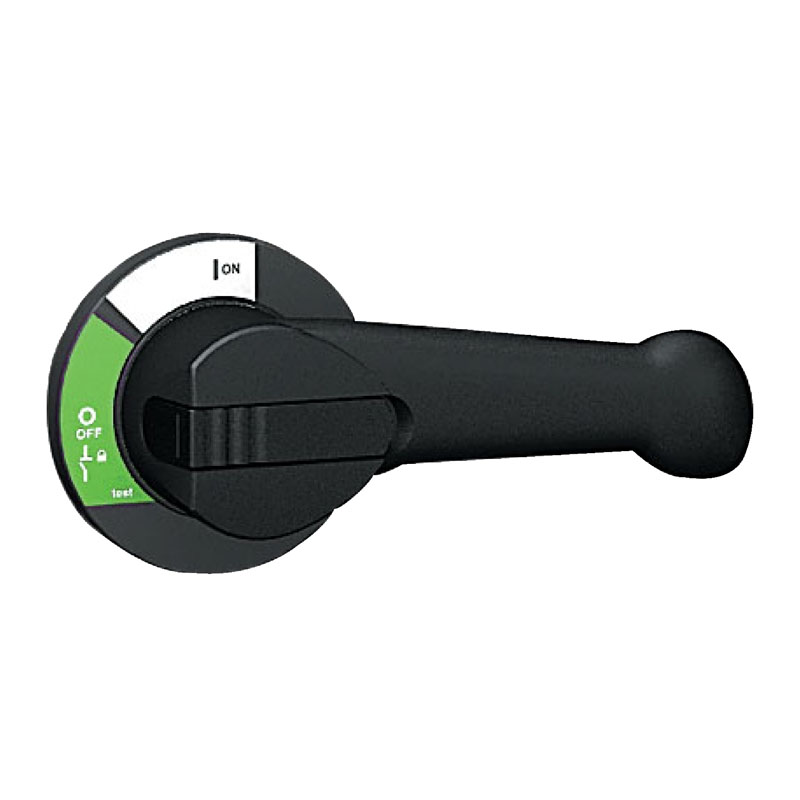
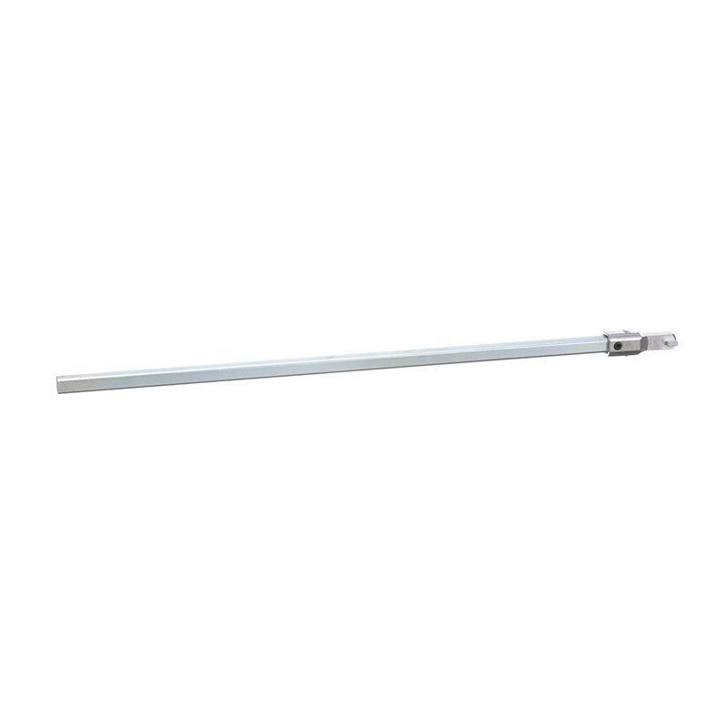
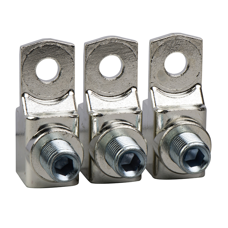
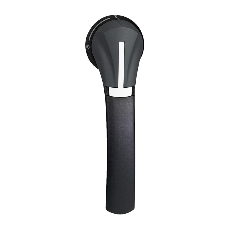
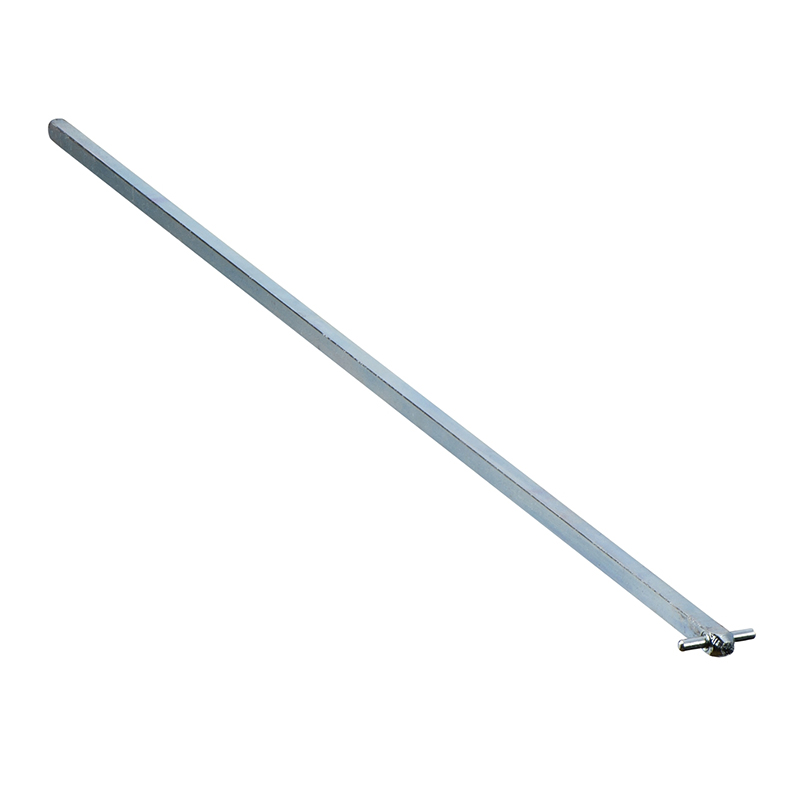
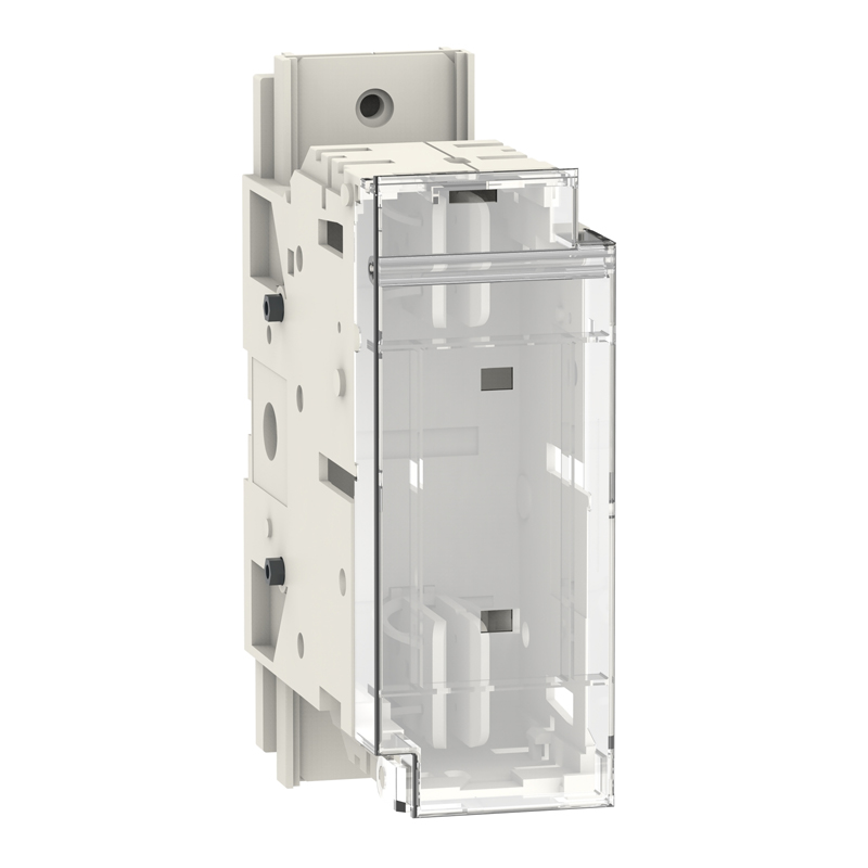
Schneider INFD-Black Extended Rotary Handle
Brand:
Series:
Fupact INFD
Attachment Description:
INFD630-INFD800, black
Attachment Type:
Control accessories
Attachment Name:
Front extended rotating handle
Model:
INFD-Black Extended Rotary Handle (630/800)
Order Number:
49620
Description:
Schneider fuse disconnect switch accessories INFD-black extended rotary handle (630/800), control accessories
Product parameters
| Product attributes | Attribute value | Filter product attributes |
|---|---|---|
| Brand: | Schneider | |
| Series: | Fupact INFD | |
| Attachment Description: | INFD630-INFD800, black | |
| Attachment Type: | Control accessories | |
| Attachment Name: | Front extended rotating handle |
Products with the same attribute : 0
Show details
Series Overview
Series Overview
Fupact INFD40 to 63
Auxiliary Contacts and Indications
Description
- A group can contain at most 2 contacts.
- NO (Normally Open contact) or NC (Normally Closed contact).
- IP20 protection class.
- Connecting terminals can be used for cables with cross - sectional areas ranging from 0.75 to 2x2.5mm².
Auxiliary Contact - Indicating the NO (Closed)/OFF (Open) Position of the Device
- Installation: Located on the left side of the device.
- Combination mode: 1 to 8 NO or NC contacts.
Auxiliary Contact - Indicating the NO (Closed)/OFF (Open)/Test (Testing) Position of the Device
- Installation: Located at the upper and lower ends between the two poles of the device.
- Combination mode: 1 to 2 NO or NC contacts (depending on the installation situation of the contacts).
“Test Indication” Auxiliary Contact
- Installation: Located at the upper end between the two poles of the device.
- Combination mode: 1 to 2 NO or NC contacts (depending on the installation situation of the contacts).
Fupact INFD160
Auxiliary Contacts and Indications
Description
- A group can contain at most 2 contacts.
- NO (Normally Open contact) or NC (Normally Closed contact).
- IP20 protection class.
- Connecting terminals can be used for cables with cross - sectional areas ranging from 0.75 to 2x2.5mm².
Auxiliary Contact - Indicating the NO (Closed)/OFF (Open) Position of the Device
- Installation: Located on the left side of the device.
- Combination mode: 1 to 8 NO or NC contacts.
Auxiliary Contact - Indicating the NO (Closed)/OFF (Open)/Test (Testing) Position of the Device
- Installation: Located at the upper and lower ends between the two poles of the device.
- Combination mode: 1 to 2 NO or NC contacts (depending on the installation situation of the contacts).
“Test Indication” Auxiliary Contact
- Installation: Located at the upper end between the two poles of the device.
- Combination mode: 1 to 2 NO or NC contacts (depending on the installation situation of the contacts).
Fupact INFD250 to 800
Auxiliary Contacts and Indications
Description
- Each block includes a NO contact (Normally Open contact) or an NC contact (Normally Closed contact).
- IP20 protection class.
- Connecting terminals, for cables with cross - sectional areas ranging from 0.75 to 2x2.5mm².
NO and NC Auxiliary Contacts - Indicating the ON (Closed)/OFF (Open) Position of the Device
For INFD250 and INFD800:
- Installation: On the left side of the device.
- Combination mode: 1 or more NO or NC contacts.
Auxiliary Contact - Indicating the ON (Closed)/OFF (Open)/Test (Testing) Position of the Device
For INFD250:
- Installation: At the upper or lower end between the two poles of the device.
- Combination mode: 1 or 4 NO or NC contacts (depending on the installation situation of the contacts).
For INFD400 - INFD800:
- Installation: At the upper end between the two poles of the device.
- Combination mode: 1 or 4 NO or NC contacts.
Auxiliary Contact for Test Position Indication
For INFD250:
- Installation: At the upper end between the two poles of the device.
- Combination mode: 1 or 2 NO or NC contacts (depending on the installation situation of the contacts).
For INFD400 - INFD800:
- Installation: At the lower end between the two poles of the device.
- Combination mode: 1 or 4 NO or NC contacts.
Fuse Link Breakage Visualization
If fuse link visualization is to be achieved, this device must be configured. It can provide the visualization function of the fuse link status. This device has:
- Send a fuse link breakage signal.
- Avoid overload faults caused by single - phase operation of the motor.
- Avoid risks caused by abnormal voltage changes on the neutral wire.
Description
For INFD250 - 800 fuse links, there are two possible blocks:
- 3 - pole (3P).
- 4 - pole (4P).
The indicator is composed of a mechanical transmission device and an adapter with 1 or 2 NO(NC) contacts.
Fupact INFD40 to 800
Fuse Link Monitor
Functions
This device can remotely process the status information of standard fuse links (without strikers). It can be used for:
- Send a breakage signal.
- Protect the motor from overload caused by single - phase operation.
- Prevent abnormal voltage from appearing on the neutral wire.
Standards
- Comply with the international standard IEC 60947 - 5 - 1.
And comply with:
- EN 50204.
- Standards related to electromagnetic compatibility (EMC) - EN 61000.
Description
- Operation of standard fuse links.
- Can be used in capacitor cabinets.
Simplified Power Supply:
- No need for a specific power supply.
- Can be applied to unbalanced phase systems.
- Powered by the fuse link on the isolating switch disconnector of the fuse.
Working Voltages for Two Different Models:
- 100...260VAC, ± 10%, 50/60Hz.
- 380...690VAC, ± 10%, 50/60Hz.
The device has passed electromagnetic compatibility (EMC) testing.
- Small size, suitable for installation in all series of isolating switch disconnector groups.
Installation:
- The optional card can be installed on INFD40 to INFD160 isolating switch disconnectors. If installed on INFD40 (disconnector), an auxiliary contact adapter frame must be purchased separately (see “INFD40 accessories INFD40 to INFD160”).
- Installation 托架 for INFD200 to INFD800.
Characteristics:
- IP20 protection class.
- Weight: 140 grams.
The product includes:
- Equipped with a fuse monitor with one NO contact and one NC contact.
- Installation 托架 for INFD200 to INFD800.
Operation
Reset:
- When the fuse link is replaced, the device will automatically reset.
Indication:
Normal Operation:
- When the fuse link is energized, the green LED is on.
- The contact is in the reset position.
When Fuse Link is Broken:
- The green LED is off, and the red LED is on.
- The contact is activated.
- The NO contact is used for remote fault indication.
- By using the NC contact, it can control undervoltage equipment,thus shutting down those devices sensitive to single - phase operation.
Fupact INFD40 to 800
Rotary Handle
Direct - Type Rotary Handle
- The direct - type rotary handle can only be used for the front handle.
- Protection class: IP20.
For INFD40 to INFD400:
- Switch the switch to the OFF position:
- Use 1 - 2 padlocks with a shackle diameter between 5 - 6mm (not provided).
- Black handle.
Emergency Disconnection Type with Red - Yellow Handle
For INFD630 to 800:
- Locked by 3 padlocks (not provided) with a shackle diameter between 5 - 10mm.
- Model:
- Standard type with black handle.
Extended Rotary Handle
- Through the front or side of the switch cabinet, it can operate the isolating switch disconnector group installed on the front of the switch cabinet.
- The extended rotary handle can be installed on the front or side of the isolating switch disconnector group.
- Protection class: IP65.
Operation
- When the isolating switch disconnector group is in the ON (Closed) position, prevent the door from opening.
- (Only for the front handle): Authorized personnel can open the lock for maintenance purposes.
- The shackle diameter is 5 to 10mm (one to three padlocks, not provided), which can lock the isolating switch disconnector group in the OFF (O) or ON (I) position. Therefore, it can prevent the switch cabinet door from being opened (only for the front).
Model
- Standard type: Black handle.
- Emergency type: Red - yellow handle.
- “Test O I” indicator.
Testing Function:
- Standard function, for the basic type INFD40 to INFD800 isolating switch disconnector group.
- When the power circuit is disconnected, by using the testing function, it can detect the control circuit.
- Place the handle in the testing position, which can operate the auxiliary test contacts and simulate the closing situation of the power circuit.
Installation
The extended rotary handle consists of the following components:
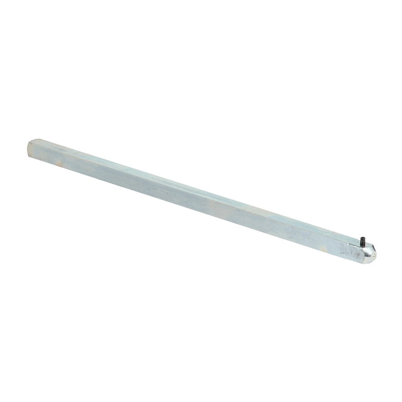
- An extendable shaft that can be cut as needed (a 430 to 465mm shaft can be selected).
- Installed on the door or the side of the switch cabinet.
To comply with the installation standard, the handle of the electrical switch device should be able to indicate:
- ON position (Closed) - vertical.
- OFF position (Open) - horizontal.
No matter whether the device is installed horizontally or vertically, the Fupact extended rotary handle can be installed parallel or vertically with the device.
Fupact INFD40 to 800
Locking Device
Locking Device - Preventing Contact with Fuse Links
The Fupact series includes a (locking) system. When the isolating switch disconnector group is in the ON (I) position, this system can lock the fuse base and the fuse chamber cover.
Locking the Device
- To lock the Fupact INFD isolating switch disconnector group in the ON or OFF position, the standard lock must be equipped with 2 or 3 padlocks (not provided).
- By locking the fuse disconnector in the OFF position, it can ensure that its isolation level complies with the IEC 60947 - 3 standard.

Rachel
Industrial Control Sales Specialist: Focuses on delivering high-performance, cost-effective industrial control products. Offers end-to-end one-stop procurement support—covering rapid quotation, streamlined order fulfillment, and responsive after-sales service—to simplify clients’ procurement processes.
Email: Anthony@icxsg.com
We offer competitive product pricing. For fast support, send your email, phone, address, and the product model & quantity you want—we’ll reach out quickly!
We typically respond via email within one business day! You can also contact us at Anthony@icxsg.com