







 English
 Français
 Deutsch
 Português
 Español
 русский
  한국어
한국어 العربية
 Italiano
 Indonesia
 Schweiz
 Polski
 Nederlands
 ישראל - עברית
 Perzisch
 ไทย
ไทย 日本語
日本語 ኢትዮ-አማርኛ
 Việt Nam
 Kiswahili
 Srpski
 Ελληνικά
 简体中文
简体中文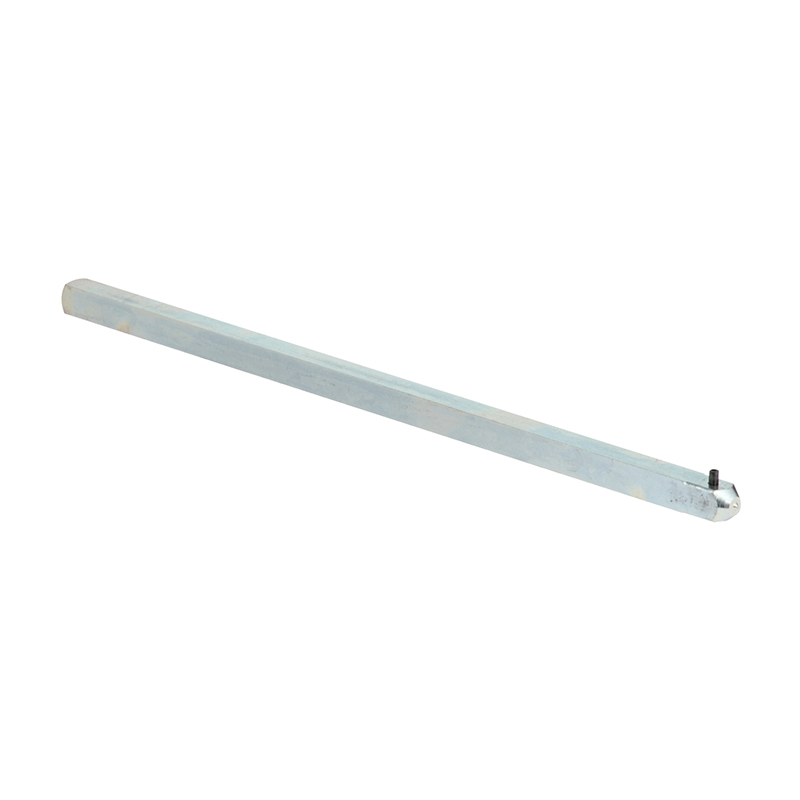
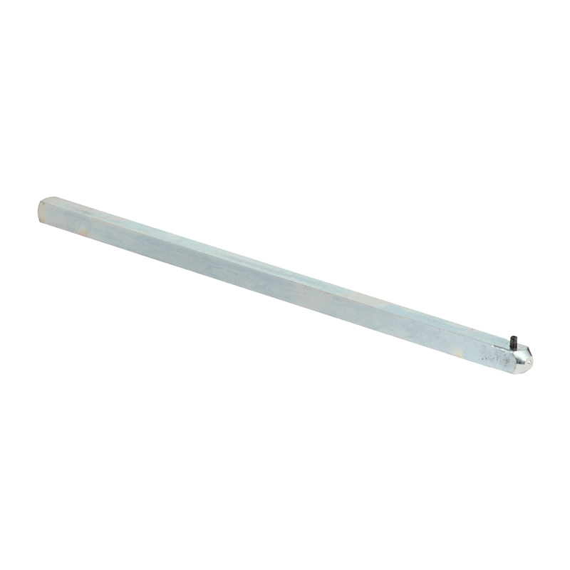
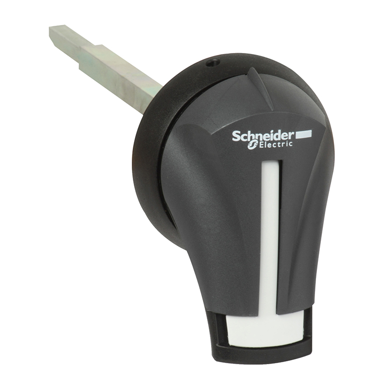
Schneider FUPACT GS 630-1250A Rotary Handle Shaft 12X12 400MM
Brand:
Series:
Fupact GS
Attachment Description:
GS630-GS1250, 400mm
Attachment Type:
Control accessories
Attachment Name:
Extension rod
Model:
FUPACT GS 630-1250A Rotating Handle Shaft 12X12 400MM
Order Number:
GS2AE51
Description:
Schneider Fuse Isolator Switch Accessories FUPACT GS 630-1250A Rotary Handle Shaft 12X12 400MM, Control Accessories
Product parameters
| Product attributes | Attribute value | Filter product attributes |
|---|---|---|
| Brand: | Schneider | |
| Series: | Fupact GS | |
| Attachment Description: | GS630-GS1250, 400mm | |
| Attachment Type: | Control accessories | |
| Attachment Name: | Extension rod |
Products with the same attribute : 0
Show details
Series Overview
Series Overview
FuPacT GS 63
Function
FuPacT GS 63 isolating switch - disconnectors are used in combination with fuses to provide overload and short - circuit protection for circuits.
They achieve the function of 切断 ing the circuit by performing double - break on the upper and lower ends of the fuse link.
They also provide a switching function to achieve on - load breaking of the circuit.
Design and Installation
The FuPacT GS 63 has a compact structure and optimized space utilization. The device consists of electrical and control mechanisms and is pre - assembled and tested at the factory.
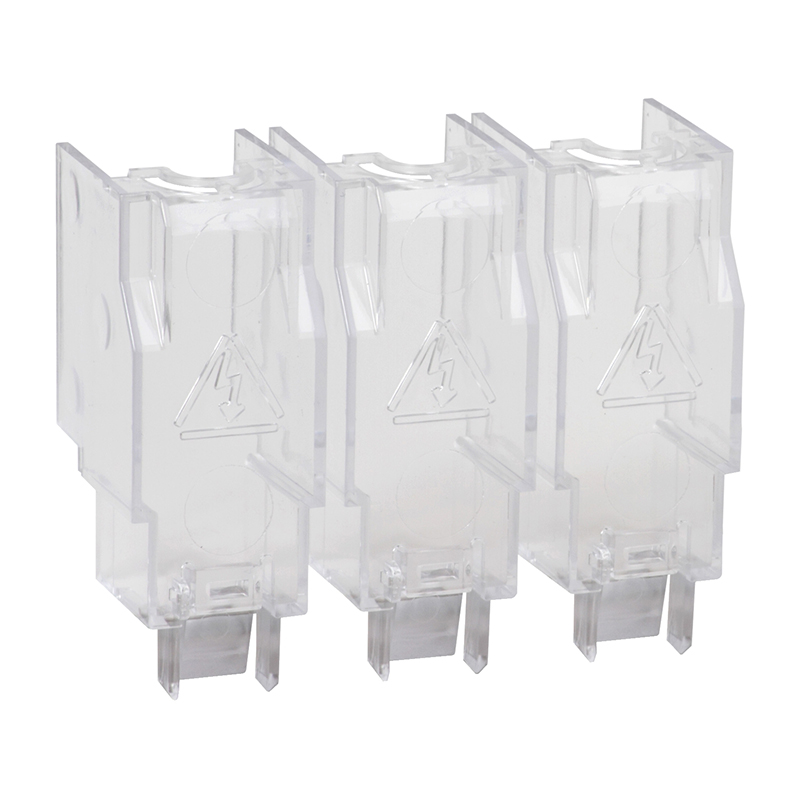
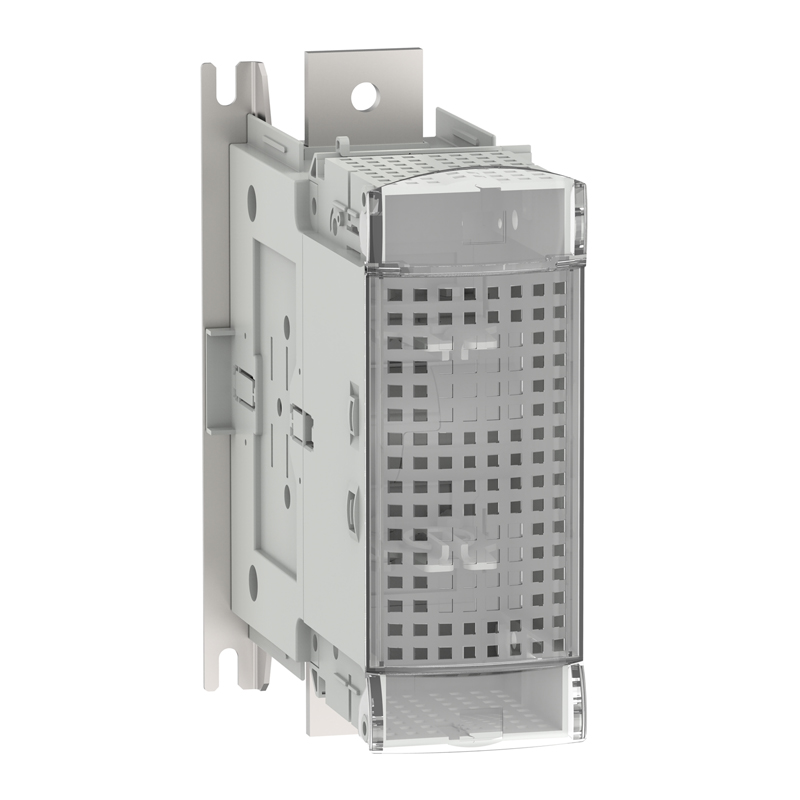
The fuse can be observed through a transparent cover to check if the fuse link is installed and its rated value.
GS 63 devices can be installed on a DIN rail or directly on a panel using pre - installed fixing points without additional accessories for panel mounting.
Pole Numbers
GS 63 provides 3 - pole and 4 - pole versions. Through separate/collective control for breaking, 3 - pole devices are equipped with 3 fuse bases to break the upper and lower ends of the fuse.
4 - pole devices are equipped with 4 fuse bases to break the upper and lower ends of the fuse, and one of them can be equipped with a neutral conductor.
Device Control
There are three control methods for the device:
- Using a direct - acting rotary handle, the handle is directly installed on the outer shell of the device's control mechanism.
- Using a front - extending control, the handle is installed on the door of the distribution cabinet.
- Using a side - extending control, the handle is installed on the side of the distribution cabinet.
The lengths of the control rods are available in three types: 200, 320, or 400mm.
There are several IP65 control handles to choose from.
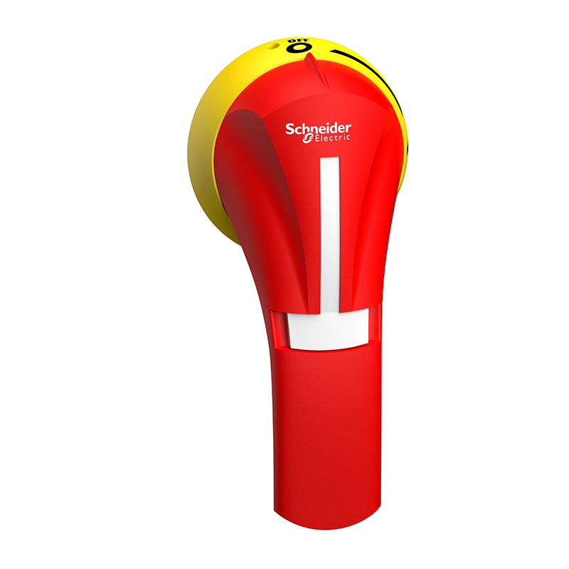
Front control handles are available in black or yellow/black colors, with or without a test position.
Side control handles are available in black or yellow/black colors, without a test position.
Front control handles can achieve the interlocking between the door and the device's control rod, preventing the door from being opened when the device is in the closed position.
Side control handles cannot achieve the interlocking between the door and the device's control rod. Using a side control handle as a front control handle is prohibited.
Locking System
Direct - acting control handles and extended control handles provide the function of locking the device in the OFF position.
Each handle can be equipped with up to 3 padlocks.
The device can also be directly locked - a padlock is locked on the control unit of the device or on the locking lug at the bottom of the control unit, and up to 3 padlocks can be used.
Using FuPact Isolating Switch - Disconnector Groups as Emergency Disconnect Devices
FuPact isolating switch - disconnectors can be used as emergency disconnect devices.
For this application, the device must be easy to observe, reach, and identify (see Standards and Specifications: VDE 0660, VDE 0113, CNOMO, etc.).
For easy identification, emergency disconnect isolating switch - disconnectors use a special color, as specified in various standards. Different from the standard version of the device:
- The front panel of the device is yellow.
- The handle is red.
The functional characteristics of FuPact emergency isolating switch - disconnector groups are the same as those of standard isolating switch - disconnector groups.
Device Connection
FuPacT GS 63 devices are equipped with screw - type terminal blocks, which can be used to connect conductors with a cross - sectional area of 16 to 25mm².
Fuse Types and Installation
GS 63 supports fuses that comply with IEC60269/NFC63320 standards, specifically DIN 000 fuses.
Note: The device is not equipped with fuses.
For GS 63, fuses are installed through a transparent protective cover. Before installation, the power must be cut off first, and then the fuse link is inserted into the fuse base.
External Neutral Conductor and Internal Neutral Connection Piece
The DIN 6334 neutral connection piece can establish a neutral connection inside the device. The connection piece replaces the fuse link for installation.
The external neutral connection piece is an electrode with a removable neutral connection piece and will not be disconnected together with other poles (no mechanical structure).
It is directly installed on the left side of the device.
Tapered Piece
The function of this accessory is to make the control rod and the opening on the cabinet door secondary. It is installed on the cabinet door and can compensate for hole misalignment or bends of the rod within ± 10mm.
Auxiliary Contacts/Interlocks
FuPacT GS 63 can be equipped with 4 auxiliary contacts to indicate the mechanical position of the device. 2 auxiliary contacts are directly installed on the device, and the other 2 auxiliary contacts are stacked on the previous 2 contacts.
In this way, the normally open auxiliary contacts can indicate the closing, opening, and testing positions of the device.
The indication test position requires a handle for the test position.
Another function of the auxiliary contacts is to indicate the pre - breaking of the device, that is, the handle has just operated but the power has not been disconnected yet.
This can realize pre - breaking of the power supply to stop energy storage.
Model GSIAM1010 and GSIAM1011 each have 1 auxiliary contact (normally open or normally closed) + 2 plastic connectors.
LV481110 has 10 plastic connectors.
FuPacT GS 125, GS 160
Function
FuPact GS 125 and GS 160 isolating switch - disconnectors are used in combination with fuses to provide overload and short - circuit protection for circuits.
They achieve the function of 切断 ing the circuit by performing double - break on the upper and lower ends of the fuse link.
They also provide a switching function to achieve on - load breaking of the circuit.
Design and Installation
FuPact GS 125 and GS 160 devices have a compact structure and maximize space utilization.
The device consists of electrical and control mechanisms and is pre - assembled and tested at the factory.
The fuse can be observed through a transparent cover to check if the fuse link is installed and its rated value.
The device can be installed on a panel, and there are no pre - installed fixing points on the product. No additional accessories are needed for panel mounting.
Pole Numbers
The device provides 3 - pole and 4 - pole versions. Through separate/collective control for breaking, 3 - pole devices are equipped with 3 fuse bases to break the upper and lower ends of the fuse.
4 - pole devices are equipped with 4 fuse bases to break the upper and lower ends of the fuse, and one of them can be equipped with a neutral conductor.
Device Control
There are three control methods for the device:
- Using a direct - acting rotary handle, the handle is directly installed on the outer shell of the device's control mechanism.
- Using a front - extending control, the handle is installed on the door of the distribution cabinet.
- Using a side - extending control, the handle is installed on the side of the distribution cabinet.
The lengths of the control rods are available in three types: 200, 320, or 400mm.
There are several IP65 control handles to choose from.
Front control handles are available in black or yellow/black colors, with or without a test position.
Side control handles are available in black or yellow/black colors, without a test position.
Front control handles can achieve the interlocking between the door and the device's control rod, preventing the door from being opened when the device is in the closed position.
Side control handles cannot achieve the interlocking between the door and the device's control rod. Using a side control handle as a front control handle is prohibited.
Locking System
Direct - acting control handles and extended control handles provide the function of locking the device in the OFF position.
Each handle can be equipped with up to 3 padlocks.
The device can also be directly locked - a padlock is locked on the control unit of the device or on the locking lug at the bottom of the control unit, and up to 3 padlocks can be used.
Using FuPact Isolating Switch - Disconnector Groups as Emergency Disconnect Devices
FuPact isolating switch - disconnectors can be used as emergency disconnect devices.
For this application, the device must be easy to observe, reach, and identify (see Standards and Specifications: VDE 0660, VDE 0113, CNOMO, etc.).
For easy identification, emergency disconnect isolating switch - disconnectors use a special color, as specified in various standards. Different from the standard version of the device:
- The front panel of the device is yellow.
- The handle is red.
The functional characteristics of FuPact emergency isolating switch - disconnector groups are the same as those of standard isolating switch - disconnector groups.
Device Connection
FuPacT GS 125 and GS 160 devices are equipped with clamp - type terminals for connecting conductors with pre - installed terminals.
The terminal blocks can be used for direct connection of conductors without busbars.
Components are pre - installed in the device and come with a busbar set.
FuPact GS 125 current connectors: GSI3AW3 (a group of 3) or GSI3AW4 (a group of 4).
Can be used for direct connection protection of FuPact GS 125: GSI3AP3 (a group of 3) or GSI3AP4 (a group of 4).
For FuPact GS 160: GSI4AP3 (a group of 3) or GSI4AP4 (a group of 4).
Fuse Types and Installation
GS 125 and GS 160 support fuses that comply with IEC60269/NFC63320 standards, specifically DIN 00 fuses.
Note: The device is not equipped with fuses.
For GS 125 and GS 160, fuses are installed through a transparent protective cover. Before installation, the power must be cut off first, and then the fuse link is inserted into the fuse base.
External Neutral Conductor and Internal Neutral Connection Piece
The DIN 125A neutral connection piece can establish a neutral connection inside the device. The connection piece replaces the fuse link for installation.
The external neutral connection piece is an electrode with a removable neutral connection piece and will not be disconnected together with other poles (no mechanical structure).
It is directly installed on the left side of the device.
Tapered Piece
The function of this accessory is to make the control rod and the opening on the cabinet door secondary. It is installed on the cabinet door and can compensate for hole misalignment or bends of the rod within ± 10mm.
Auxiliary Contacts/Interlocks
FuPacT GS 125 and GS 160 devices can be equipped with 4 auxiliary contacts to indicate the mechanical position of the device. 2 auxiliary contacts are directly installed on the device, and the other 2 auxiliary contacts are stacked on the previous 2 contacts.
In this way, the normally open auxiliary contacts can indicate the closing, opening, and testing positions of the device.
The indication test position requires a handle for the test position.
Another function of the auxiliary contacts is to indicate the pre - breaking of the device, that is, the handle has just operated but the power has not been disconnected yet.
This can realize pre - breaking of the power supply to stop energy storage.
Model GSIAM1010 and GSIAM1011 each have 1 auxiliary contact (normally open or normally closed) + 2 plastic connectors.
LV481110 has 10 plastic connectors.
FuPacT GS 250, GS 400
Function
FuPact GS 250 and GS 400 isolating switch - disconnectors are used in combination with fuses to provide overload and short - circuit protection for circuits.
They achieve the function of cutting the circuit by performing double - break on the upper and lower ends of the fuse link.
They also provide a switching function to achieve on - load breaking of the circuit.
Design and Installation
FuPact GS 250 and GS 400 devices have a compact structure and maximize space utilization.
The device consists of electrical and control mechanisms and is pre - assembled and tested at the factory.
The fuse can be observed through a transparent cover to check if the fuse link is installed and its rated value.
The device can be installed on a panel, and there are no pre - installed fixing points on the product. No additional accessories are needed for panel mounting.
Pole Numbers
The device provides 3 - pole and 4 - pole versions. Through separate/collective control for breaking, 3 - pole devices are equipped with 3 fuse bases to break the upper and lower ends of the fuse.
4 - pole devices are equipped with 4 fuse bases to break the upper and lower ends of the fuse, and one of them can be equipped with a neutral conductor.
Device Control
There are three control methods for the device:
- Using a direct - acting rotary handle, the handle is directly installed on the outer shell of the device's control mechanism.
- Using a front - extending control, the handle is installed on the door of the distribution cabinet.
- Using a side - extending control, the handle is installed on the side of the distribution cabinet.
The lengths of the control rods are available in three types: 200, 320, or 400mm.
There are several IP65 control handles to choose from.
Front control handles are available in black or yellow/black colors, with or without a test position.
Side control handles are available in black or yellow/black colors, without a test position.
Front control handles can achieve the interlocking between the door and the device's control rod, preventing the door from being opened when the device is in the closed position.
Side control handles cannot achieve the interlocking between the door and the device's control rod. Using a side control handle as a front control handle is prohibited.
Locking System
Direct - acting control handles and extended control handles provide the function of locking the device in the OFF position.
Each handle can be equipped with up to 3 padlocks.
The device can also be directly locked - a padlock is locked on the control unit of the device or on the locking lug at the bottom of the control unit, and up to 3 padlocks can be used.
Using FuPact Isolating Switch - Disconnector Groups as Emergency Disconnect Devices
FuPact isolating switch - disconnectors can be used as emergency disconnect devices.
For this application, the device must be easy to observe, reach, and identify (see Standards and Specifications: VDE 0660, VDE 0113, CNOMO, etc.).
For easy identification, emergency disconnect isolating switch - disconnectors use a special color, as specified in various standards. Different from the standard version of the device:
- The front panel of the device is yellow.
- The handle is red.
The functional characteristics of FuPact emergency isolating switch - disconnector groups are the same as those of standard isolating switch - disconnector groups.
Device Connection
FuPact GS 250 and GS 400 devices are equipped with clamp - type terminals for connecting conductors with pre - installed terminals.
The terminal blocks can be used for direct connection of conductors without busbars.
Components are pre - installed in the device and come with a busbar set.
FuPact GS 250 current connectors: GSI3AW3 (a group of 3) or GSI3AW4 (a group of 4).
Can be used for direct connection protection of FuPact GS 250: LV481203 (a group of 3) or LV481204 (a group of 4).
For FuPact GS 250 and GS 400:
- GSI3AP3 (a group of 3)
- GSI3AP4 (a group of 4)
Fuse Types and Installation
GS 250 supports fuses that comply with IEC60269/NFC63320 standards, specifically DIN 1 fuses.
GS 400 supports fuses that comply with IEC60269/NFC63320 standards, specifically DIN 2 fuses.
Note: The device is not equipped with fuses.
For GS 250 and GS 400, fuses are installed through a transparent protective cover. Before installation, the power must be cut off first, and then the fuse link is inserted into the fuse base.
External Neutral Conductor and Internal Neutral Connection Piece
The DIN 250 and DIN 400 neutral connection pieces can establish a neutral connection inside the device. The connection piece replaces the fuse link for installation.
The external neutral connection piece is an electrode with a removable neutral connection piece and will not be disconnected together with other poles (no mechanical structure).
It is directly installed on the left side of the device.
Tapered Piece
The function of this accessory is to make the control rod and the opening on the cabinet door secondary. It is installed on the cabinet door and can compensate for hole misalignment or bends of the rod within ± 10mm.
Auxiliary Contacts/Interlocks
FuPact GS 250 and GS 400 devices can be equipped with 8 auxiliary contacts to indicate the mechanical position of the device. 4 auxiliary contacts are directly installed on the device, and the other 4 auxiliary contacts are stacked on the previous 4 contacts.
In this way, the normally open auxiliary contacts can indicate the closing, opening, and testing positions of the device.
Note: If a direct - acting control handle LV481702 with an auxiliary contact protection cover is used, only 4 auxiliary contacts can be used.
The indication test position requires a handle for the test position.
Another function of the auxiliary contacts is to indicate the pre - breaking of the device, that is, the handle has just operated but the power has not
disconnected yet.
This can realize pre - breaking of the power supply to stop energy storage.
Model GSIAM1010 and GSIAM1011 each have 1 auxiliary contact (normally open or normally closed) + 2 plastic connectors.
LV481110 has 10 plastic connectors.
FuPact GS 630, GS 800
Function
FuPact GS 630 and GS 800 isolating switch - disconnectors are used in combination with fuses to provide overload and short - circuit protection for circuits.
They achieve the function of cutting the circuit by performing double - break on the upper and lower ends of the fuse link.
They also provide a switching function to achieve on - load breaking of the circuit.
Design and Installation
GS 630 and GS 800 have a compact structure and maximize space utilization.
The device consists of electrical and control mechanisms and is pre - assembled and tested at the factory.
The fuse can be observed through a transparent cover to check if the fuse link is installed and its rated value.
The device can be installed on a panel, and there are pre - installed fixing points on the product. No additional accessories are needed for panel mounting.
Note: Due to the heavy equipment, 2 people may be required for panel mounting.
Pole Numbers
The device provides 3 - pole and 4 - pole versions. Through separate/collective control for breaking, 3 - pole devices are equipped with 3 fuse bases to break the upper and lower ends of the fuse.
4 - pole devices are equipped with 4 fuse bases to break the upper and lower ends of the fuse, and one of them can be equipped with a neutral conductor.
Device Control
There are three control methods for the device:
- Using a direct - acting rotary handle, the handle is directly installed on the outer shell of the device's control mechanism.
- Using a front - extending control, the handle is installed on the door of the distribution cabinet.
- Using a side - extending control, the handle is installed on the side of the distribution cabinet.
The lengths of the control rods are available in three types: 200, 320, or 400mm.
There are several IP65 control handles to choose from.
Front control handles are available in black or yellow/black colors, with or without a test position.
Side control handles are available in black or yellow/black colors, without a test position.
Front control handles can achieve the interlocking between the door and the device's control rod, preventing the door from being opened when the device is in the closed position.
Side control handles cannot achieve the interlocking between the door and the device's control rod. Using a side control handle as a front control handle is prohibited.
Locking System
Direct - acting control handles and extended control handles provide the function of locking the device in the OFF position.
Each handle can be equipped with up to 3 padlocks.
The device can also be directly locked - a padlock is locked on the control unit of the device or on the locking lug at the bottom of the control unit, and up to 3 padlocks can be used.
Using FuPact Isolating Switch - Disconnector Groups as Emergency Disconnect Devices
FuPact isolating switch - disconnectors can be used as emergency disconnect devices.
For this application, the device must be easy to observe, reach, and identify (see Standards and Specifications: VDE 0660, VDE 0113, CNOMO, etc.).
For easy identification, emergency disconnect isolating switch - disconnectors use a special color, as specified in various standards. Different from the standard version of the device:
- The front panel of the device is yellow.
- The handle is red.
The functional characteristics of FuPact emergency isolating switch - disconnector groups are the same as those of standard isolating switch - disconnector groups.
Device Connection
FuPact GS 630 and GS 800 devices are equipped with clamp - type terminals for connecting conductors with pre - installed terminals.
For convenient connection, the terminal blocks can be rotated.
Can be used for direct connection protection of FuPact GS 630 and GS 800:
- GSI3AP3 (a group of 3)
- GSI3AP4 (a group of 4)
Fuse Types and Installation
GS 630 supports fuses that comply with IEC60269/NFC63320 standards, specifically DIN 3 fuses.
GS 800 supports fuses that comply with IEC60269/NFC63320 standards, specifically DIN 4 fuses.
Note: The device is not equipped with fuses.
For GS 630 and GS 800, fuses are installed through a transparent protective cover. Before installation, the power must be cut off first, and then the fuse link is inserted into the fuse base.
External Neutral Conductor and Internal Neutral Connection Piece
The DIN 630 and DIN 800 neutral connection pieces can establish a neutral connection inside the device. The connection piece replaces the fuse link for installation.
The external neutral connection piece is an electrode with a removable neutral connection piece and will not be disconnected together with other poles (no mechanical structure).
It is directly installed on the left side of the device.
Tapered Piece
The function of this accessory is to make the control rod and the opening on the cabinet door secondary. It is installed on the cabinet door and can compensate for hole misalignment or bends of the rod within ± 10mm.
Auxiliary Contacts/Interlocks
FuPact GS 630 and GS 800 devices can be equipped with 8 auxiliary contacts to indicate the mechanical position of the device. 4 auxiliary contacts are directly installed on the device, and the other 4 auxiliary contacts are stacked on the previous 4 contacts.
In this way, the normally open auxiliary contacts can indicate the closing, opening, and testing positions of the device.
Another function of the auxiliary contacts is to indicate the pre - breaking of the device, that is, the handle has just operated but the power has not been disconnected yet.
This can realize pre - breaking of the power supply to stop energy storage.
Model GSIAM1010 and GSIAM1011 each have 1 auxiliary contact (normally open or normally closed) + 2 plastic connectors.
LV481110 has 10 plastic connectors.
FuPact GS 1250
Function
FuPact GS 1250 isolating switch - disconnectors are used in combination with fuses to provide overload and short - circuit protection for circuits.
They achieve the function of cutting the circuit by performing double - break on the upper and lower ends of the fuse link.
They also provide a switching function to achieve on - load breaking of the circuit.
Design and Installation
GS 1250 has a compact structure and maximizes space utilization.
The device consists of electrical and control mechanisms and is pre - assembled and tested at the factory.
The fuse can be observed through a transparent cover to check if the fuse link is installed and its rated value.
The device can be installed on a panel, and there are pre - installed fixing points on the product. No additional accessories are needed for panel mounting.
Note: Due to the heavy equipment, 2 people may be required for panel mounting.
Pole Numbers
The device provides 3 - pole and 4 - pole versions. Through separate/collective control for breaking, 3 - pole devices are equipped with 3 fuse bases to break the upper and lower ends of the fuse.
4 - pole devices are equipped with 4 fuse bases to break the upper and lower ends of the fuse, and one of them can be equipped with a neutral conductor.
Device Control
There are three control methods for the device:
- Using a direct - acting rotary handle, the handle is directly installed on the outer shell of the device's control mechanism.
- Using a front - extending control, the handle is installed on the door of the distribution cabinet.
- Using a side - extending control, the handle is installed on the side of the distribution cabinet.
The lengths of the control rods are available in three types: 200, 320, or 400mm.
There are several IP65 control handles to choose from.
Front control handles are available in black or yellow/black colors, with or without a test position.
Side control handles are available in black or yellow/black colors, without a test position.
Front control handles can achieve the interlocking between the door and the device's control rod, preventing the door from being opened when the device is in the closed position.
Side control handles cannot achieve the interlocking between the door and the device's control rod. Using a side control handle as a front control handle is prohibited.
Locking System
Direct - acting control handles and extended control handles provide the function of locking the device in the OFF position.
Each handle can be equipped with up to 3 padlocks.
The device can also be directly locked - a padlock is locked on the control unit of the device or on the locking lug at the bottom of the control unit, and up to 3 padlocks can be used.
Using FuPact Isolating Switch - Disconnector Groups as Emergency Disconnect Devices
FuPact isolating switch - disconnectors can be used as emergency disconnect devices.
For this application, the device must be easy to observe, reach, and identify (see Standards and Specifications: VDE 0660, VDE 0113, CNOMO, etc.).
For easy identification, emergency disconnect isolating switch - disconnectors use a special color, as specified in various standards. Different from the standard version of the device:
- The front panel of the device is yellow.
- The handle is red.
The functional characteristics of FuPact emergency isolating switch - disconnector groups are the same as those of standard isolating switch - disconnector groups.
Device Connection
FuPact GS 1250 devices are equipped with clamp - type terminals for connecting conductors with pre - installed terminals.
For convenient connection, the terminal blocks can be rotated.
Can be used for direct connection protection of FuPact GS 1250:
- GSI3AP3 (a group of 3)
- GSI3AP4 (a group of 4)
Fuse Types and Installation
GS 1250 supports fuses that comply with IEC60269/NFC63320 standards, specifically DIN 4 fuses.
Note: The device is not equipped with fuses.
For GS 1250, fuses are installed through a transparent protective cover. Before installation, the power must be cut off first, and then the fuse link is inserted into the fuse base.
External Neutral Conductor and Internal Neutral Connection Piece
The DIN 1250 neutral connection piece can establish a neutral connection inside the device. The connection piece replaces the fuse link for installation.
The external neutral connection piece is an electrode with a removable neutral connection piece and will not be disconnected together with other poles (no mechanical structure).
It is directly installed on the left side of the device.
Tapered Piece
The function of this accessory is to make the control rod and the opening on the cabinet door secondary. It is installed on the cabinet door and can compensate for hole misalignment or bends of the rod within ± 10mm.
Auxiliary Contacts/Interlocks
FuPact GS 1250 devices can be equipped with 8 auxiliary contacts to indicate the mechanical position of the device. 4 auxiliary contacts are directly installed on the device, and the other 4 auxiliary contacts are stacked on the previous 4 contacts.
In this way, the normally open auxiliary contacts can indicate the closing, opening, and testing positions of the device.
Another function of the auxiliary contacts is to indicate the pre - breaking of the device, that is, the handle has just operated but the power has not been disconnected yet.
This can realize pre - breaking of the power supply to stop energy storage.
Model GSIAM1010 and GSIAM1011 each have 1 auxiliary contact (normally open or normally closed) + 2 plastic connectors.
LV481110 has 10 plastic connectors.

Rachel
Industrial Control Sales Specialist: Focuses on delivering high-performance, cost-effective industrial control products. Offers end-to-end one-stop procurement support—covering rapid quotation, streamlined order fulfillment, and responsive after-sales service—to simplify clients’ procurement processes.
Email: Anthony@icxsg.com
We offer competitive product pricing. For fast support, send your email, phone, address, and the product model & quantity you want—we’ll reach out quickly!
We typically respond via email within one business day! You can also contact us at Anthony@icxsg.com