






 English
 Français
 Deutsch
 Português
 Español
 русский
  한국어
한국어 العربية
 Italiano
 Indonesia
 Schweiz
 Polski
 Nederlands
 ישראל - עברית
 Perzisch
 ไทย
ไทย 日本語
日本語 ኢትዮ-አማርኛ
 Việt Nam
 Kiswahili
 Srpski
 Ελληνικά
 简体中文
简体中文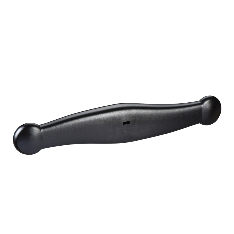
Schneider INS2000-2500 Load Isolation Switch Accessories
Brand:
Series:
INS
Attachment Type:
Control accessories
Attachment Name:
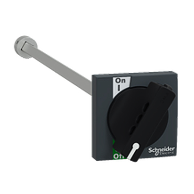
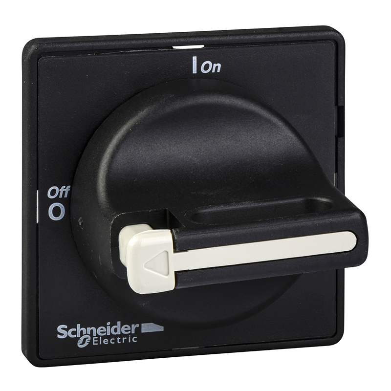
Direct rotary handle
Model:
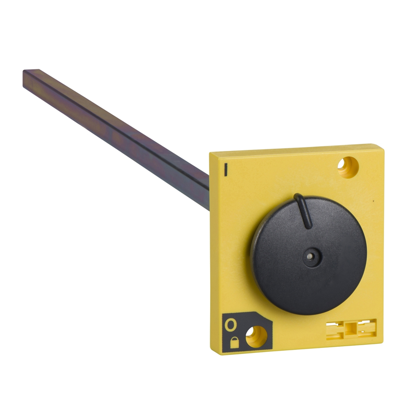
INS2000-2500 Black Handle (31298)
Order Number:
31298
Description:
Schneider INS2000-2500 black handle, control accessories, direct rotary handle, INS2000, INS2500, black
Product parameters
| Product attributes | Attribute value | Filter product attributes |
|---|---|---|
| Brand: | Schneider | |
| Series: | INS | |
| Attachment Description: | INS2000, INS2500, black | |
| Attachment Type: | Control accessories | |
| Attachment Name: | Direct rotary handle |
Products with the same attribute : 0
Show details
Series Overview
Series Overview
Connection Accessories
Connection of Terminals with Laminated Busbars or Cable Front Ends
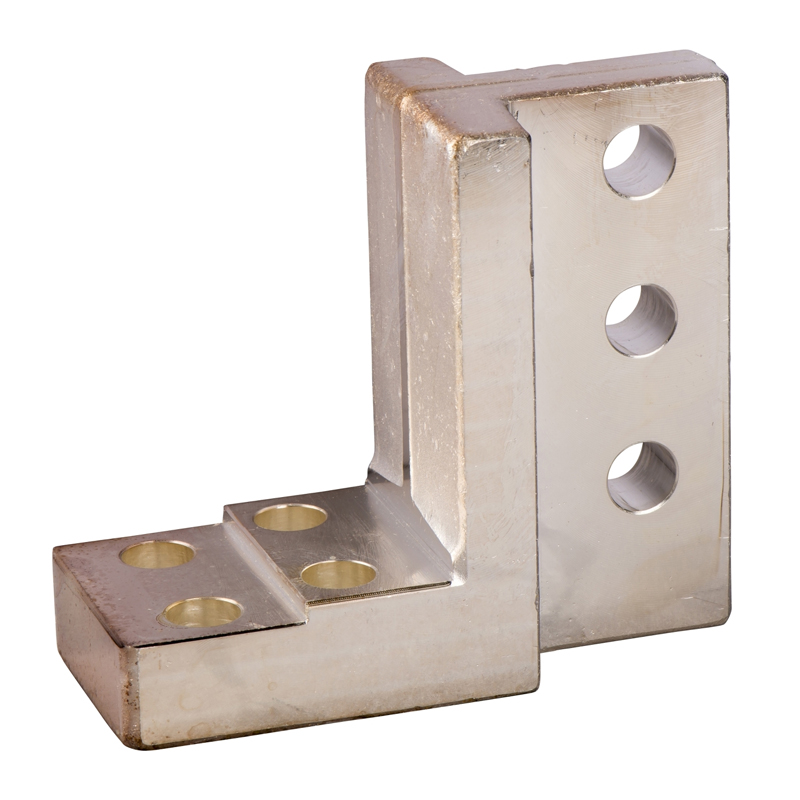
- Compact INS/INV250 to 630 isolating switches are all equipped with terminals that can use captive nuts and screws (for INS/INV below 250, M8 is used; for 320 and above, M10 is used) for direct connection with insulated busbars with lugs or cables. Terminal extenders (right - angle, vertical, extenders) are used to solve all connection problems. For Compact INS630 isolating switches, what is most needed is an extender with a 52.5 or 70mm spacing.
Lugs
-
The lugs used for copper and aluminum cables are different.
-
They are supplied with phase - spacing plates and can use long - type terminal covers.
-
Small lugs for copper cables can be used for cables with the following cross - sectional areas:
- Cables:
- 120, 150 or 185mm² (INS/INV below 250)
- 240 or 300mm² (INS/INV below 630)
- Fasten the lugs by means of hexagon pressure or square pressure.
- For direct terminal extension of INS250
- Cables:
-
Small lugs for aluminum cables can be used for cables with the following cross - sectional areas:
- 150 or 185mm² (INS/INV below 250)
- 240 or 300mm² (INS/INV below 630)
- Fasten the lugs by means of hexagon direct pressure.
Extenders
- Extenders increase the spacing between terminals. They cannot be used simultaneously with terminal covers. The integrated extender increases the spacing between terminals corresponding to the spacing of incoming line equipment and provides protection against direct contact.
Front - end Connection of Bare Cables
- Bare cables for Compact INS/INV isolating switches can be either copper cables or aluminum cables.
Single - cable Connectors for Compact INS/INV250
- The connector will be directly clamped to the equipment terminal or on the right - angle and straight - type terminal extenders and extenders.
Single - cable and Double - cable Connectors for Compact INS/INV320 to 630
- The connector is connected to the equipment terminal or right - angle extender by screws.
Distribution Connectors for Compact INS/INV250
- These connectors are directly clamped to the equipment terminals by screws. Phase - spacing plates are provided with the distribution connectors, but can also be replaced by long - type terminal covers. Each connector can accommodate 6 cables with cross - sectional areas from 1.5 to 35 mm².
Rear Connection
- The rear - end connection of cables with lugs or busbars can have two lengths. The busbar can be placed flat, vertically or at a 45° angle, depending on how the connector is placed.
- The rear connection can be easily installed on the equipment connection terminal. All combinations of rear connection length and position can be realized on a given isolating switch. The isolating switch is installed on a base plate.
- For the connection of cables without lugs, the single - cable connector for Compact INS/INV250 can be easily clamped on the rear connection.
Integrated Extender
- The connection of thick cables may require increasing the distance between the terminals of the isolating switch. It has the following characteristics:
- Increase the spacing between the terminals of the isolating switch according to the incoming line equipment.
- Can be used with all accessories for incoming line equipment connection and insulation (connectors, terminal extenders, etc.).
- Compared with the standard extender, it increases the phase - to - phase insulation distance.
Installation
- When equipped with an integrated extender, INS and INV isolating switches can be installed on the 配电盘 (power distribution panel) base or on the front panel with a pre - determined positioning base plate.
- In this way, equipment of different structural sizes can be installed neatly on the distribution cabinet.
- The same installation plate can be used for all equipment.
Insulation of Live Parts
Terminal Covers for INS and INV Isolating Switches
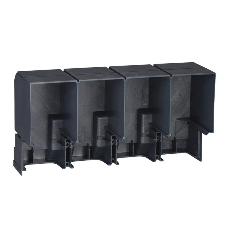
- Aluminum - sealed insulation accessories are used to prevent direct contact with the circuit.
- Protection class: IP40, IK07
- Provide aluminum - sealed accessories
Phase - spacing Plates for INS and INV
- Safety accessories provide the highest insulation between power connections.
- Realize simple installation by clamping on the body.
- Can be combined with all other connection accessories, except terminal covers and terminal box covers.
Terminal Box Covers for INS40 to INS160
- These insulation accessories are used to prevent direct contact with the cable connection screws. An insulation plate (not provided) can also be attached to this cover to avoid any contact with the power lead.
Spare Viewport for Compact INV
- Electrical corrosion will make the viewport become yellow. To maintain the visible break - point function, a new viewport should be installed.
Connection Components
- This accessory can simplify the connection of busbars or cables with lugs when connecting two Compact INS/INV100 to 630 isolating switches of the same size.
- Spacing between output terminals:
- Compact INS250 and INV100 to 250: 35mm
- Compact INS/INV320 to 630: 45mm
Auxiliary Contacts
Compact INS and INV
- 1 or 4 common - point changeover contacts can be used for remote indication of the isolating switch status information, electrical interlocking, relays, etc.
Functions
- Each contact can be used for the following functions:
- OF (ON/OFF): Indicate the position of the isolating switch handle.
- CAM (Pre - closing or Pre - breaking Function): Indicate the position of the handle.
- Especially used for:
- CAO Pre - breaking Switch (auxiliary contact breaks before the main contact breaks), for example, used to automatically open a circuit breaker or a contactor before opening Compact INS.
- CAF Pre - closing Switch (auxiliary contact closes before the main contact closes).
- Switch very small loads. There is a “low - standard” type that can be used to switch very small loads (for example, control PLC or electronic circuits).
Standard
- Auxiliary contacts comply with the international standard IEC60947 - 5 - 1.
Installation
- They are simply clamped under the accessory cover (label) of the isolating switch.
Insulation
- Can seal the auxiliary protective cover to prevent direct contact with the power circuit.
Current Measurement
Ammeter Module
- Used for Compact INS250 to 630 and INV100 to 630.
Functions
- Measure and display the current value of each phase on the pointer ammeter (selected by the three - position switch on the front panel).
Installation
- Directly connected to the outgoing terminals of the isolating switch (except for the installation of INS250 with a direct handle).
- The ammeter is clamped on the module in any of the 4 90° positions, that is, the isolating switch can be installed horizontally or vertically.
- Protection class: IP40 IK04
- Front end and main circuit II - class insulation
Electrical Characteristics
- Accuracy class 4.5.
Current Transformer Module
- Used for Compact INS250 to 630 and INV100 to 630.
Functions
- Used to measure current for supply to analog meters or DigiPact IM or PM modules to display current values.
Installation
- Directly connected to the outgoing terminals of the isolating switch.
- Protection class: IP40, IK07
- Front panel and main circuit II - class insulation
- Through 6 built - in terminals for cables with a cross - sectional area of 2.5mm².
Electrical Characteristics
- Secondary side current 5A current transformer.
- Accuracy class 3, power consumption as follows:
- 100A - 1.6VA
- 150A - 3VA
- 250A - 5VA
- 400/630A - 8VA
Rotary Handle
Direct Rotary Handle
- Protection class IP40, IK07
- Use 1 to 3 padlocks to lock the isolating switch in the OFF position. The shackle diameter is 5 to 8mm (not provided).
Model
- Standard type, with a black handle.
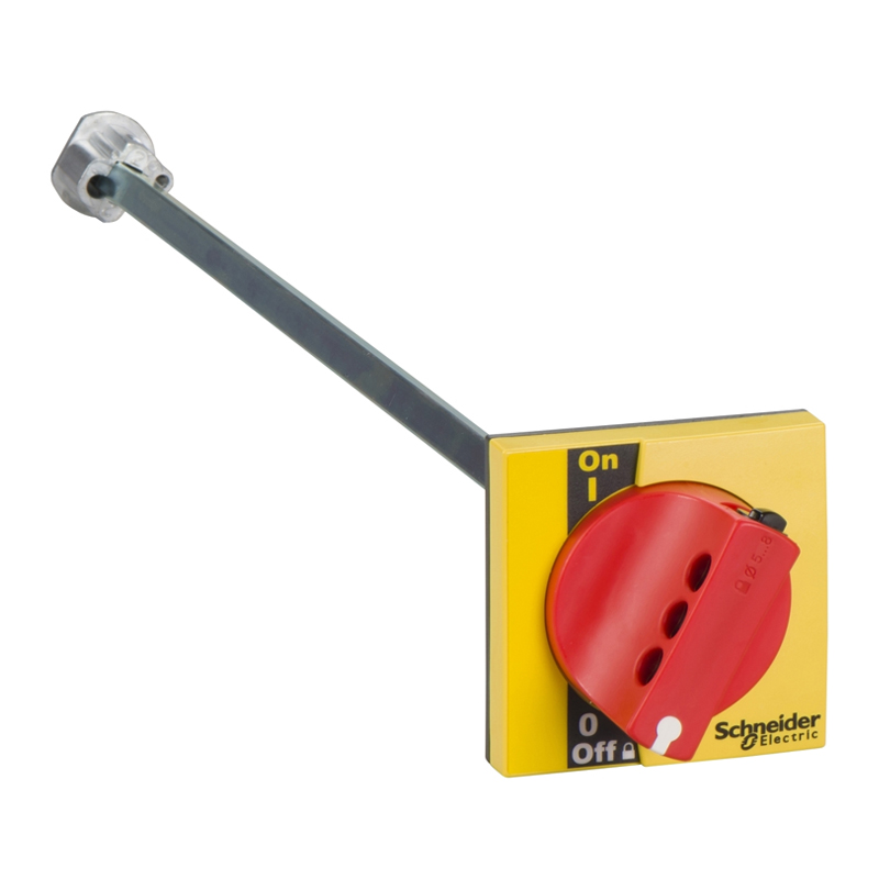
- Emergency breaking type: with a red handle for machine tool control and a yellow front panel.
Extended Rotary Handle
- Installed inside the distribution panel, it can realize the operation of the isolating switch on the front or side of the distribution panel. The extended rotary handle can be installed on the front and side of the isolating switch. Protection class IP55, IK08.
Operation
- Maintain insulation usability.
- Prevent the door from opening when the isolating switch is in the ON position (only for the front handle).
- Use 1 to 3 padlocks to lock the isolating switch in the OFF position. The shackle diameter is 5 to 8mm (not provided). Locking can prevent the distribution panel door from opening (only for the front handle).
Model
- Standard type: use a black handle.
- Emergency breaking type: use a red handle and a yellow front panel for machine tool control.
Installation
- The extended rotary handle consists of the following parts:
- A part that can replace the direct rotary handle of the Compact isolating switch (fastened by screws).
- A part (handle and front panel) installed on the front or side of the distribution panel. Regardless of whether the isolating switch is installed vertically or horizontally, this part is fastened in the same position.
- An adjustable extension shaft.
Locking Device
Padlock Locking
- Applicable to INS40 to 250A and INV100 to 250A.
- The isolating switch can be locked in the OFF position.
- The handle can have a maximum of 3 padlocks (not provided).
- Locking in the OFF position ensures the highest level specified by IEC 60947 - 3. The handle can also be locked in the OFF position. Locking in the OFF position ensures the spacing specified by IEC 60947 - 3.
Key Locking
- Applicable to INS250 - 100 to 250A and INV100 to 630.
- Use a lock cylinder (optional) to lock INS250 to 630, INV100 to 250, and the isolating switch in the OFF position. This lock can be installed in the pre - reserved hole on the front of the equipment.
- When the isolating switch is in the ON position, the key cannot be removed.
- The key cylinder can also be installed on the isolating switch equipped with an extended rotary handle.

Rachel
Industrial Control Sales Specialist: Focuses on delivering high-performance, cost-effective industrial control products. Offers end-to-end one-stop procurement support—covering rapid quotation, streamlined order fulfillment, and responsive after-sales service—to simplify clients’ procurement processes.
Email: Anthony@icxsg.com
We offer competitive product pricing. For fast support, send your email, phone, address, and the product model & quantity you want—we’ll reach out quickly!
We typically respond via email within one business day! You can also contact us at Anthony@icxsg.com