






 English
 Français
 Deutsch
 Português
 Español
 русский
  한국어
한국어 العربية
 Italiano
 Indonesia
 Schweiz
 Polski
 Nederlands
 ישראל - עברית
 Perzisch
 ไทย
ไทย 日本語
日本語 ኢትዮ-አማርኛ
 Việt Nam
 Kiswahili
 Srpski
 Ελληνικά
 简体中文
简体中文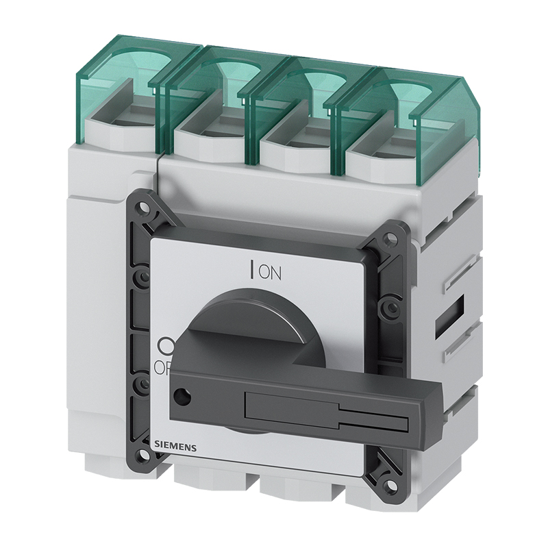
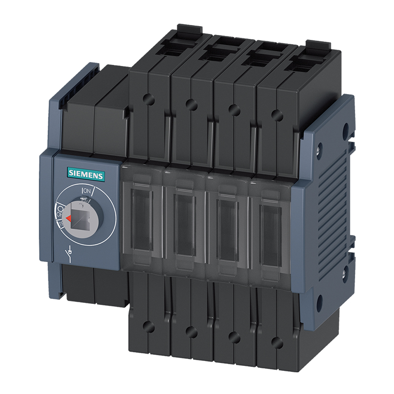
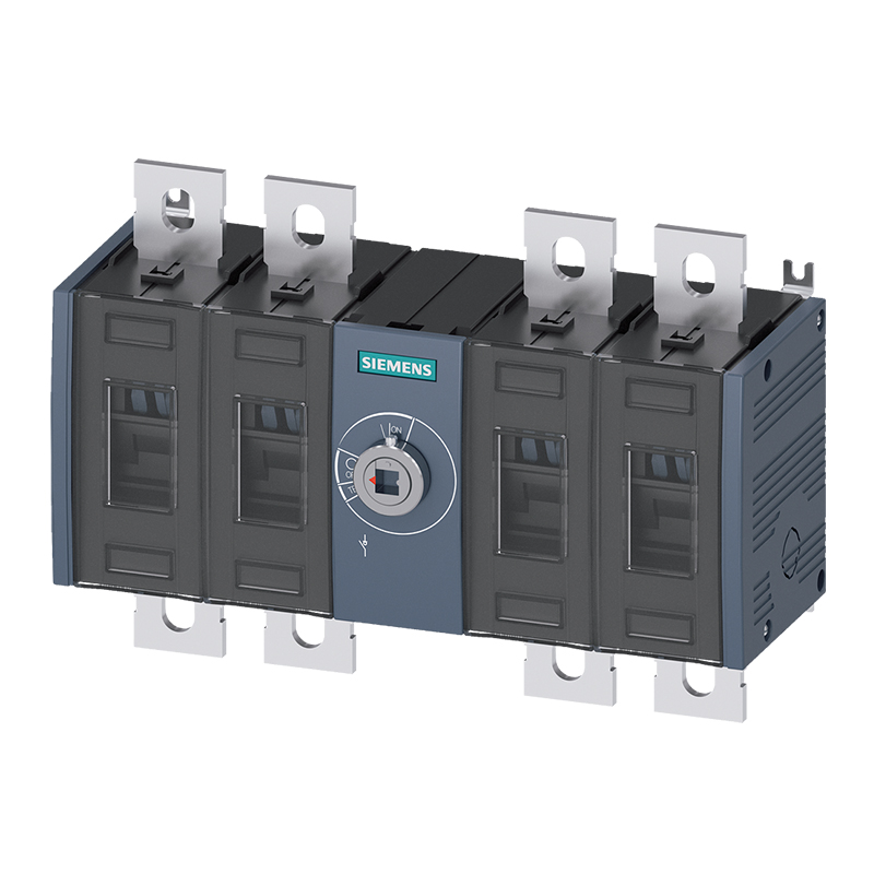
Siemens 3LD2305-1TL11 load disconnect switch
Brand:
Series:
3LD2
On/Off Load Type:
Resistive load/motor load
Handle Type:
Frontal Operation
How It Works:
Manual Operation
Rated Current:
160A
Poles:
3P+N
Rated Voltage:
690VAC
Installation:
Four-hole installation
Model:
3LD2305-1TL11
Order Number:
3LD23051TL11
Description:
Siemens 3LD2305-1TL11, manual operation, front operation, resistive load/motor load, 3P+N, four-hole installation, 690VAC
Product parameters
| Product attributes | Attribute value | Filter product attributes |
|---|---|---|
| Brand: | Siemens | |
| Series: | 3LD2 | |
| On/Off Load Type: | Resistive load/motor load | |
| Handle Type: | Frontal Operation | |
| How It Works: | Manual Operation | |
| Rated Current: | 160A | |
| Poles: | 3P+N | |
| Rated Voltage: | 690VAC | |
| Installation: | Four-hole installation |
Products with the same attribute : 0
Show details
Series Overview
Series Overview
- The 3LD main controller and emergency stop switch are manually operated load - break switches, complying with IEC 60947 standard and VDE 3 Part 0660 (EN 107 - 60947), and meeting the conditions for load - break switches.
- In the EN 60204 - 1 standard (VDE 0113 Part 1), the main switch is called the "isolation device" and the emergency stop switch is called the "emergency shutdown device".
- The 3LD switches from 16 - 250 A comply with UL508 certification and can be used as "manual motor controllers" and "motor isolation devices". The 3LD isolating switch has also obtained CCC certification.
- Using padlocks (up to 3 can be installed), maintenance personnel can prevent unauthorized startup.
- The 3LD switch can be used in any installation position.
Application
- 3LD switches can not only be used to switch main circuits and auxiliary circuits, but also can be used to switch inductive motors and other loads during maintenance and repair.
- They can be used as:
- ON - OFF switches
- Emergency stop switches
- Switch position indicators:
- The main control switch complies with the EN 60204 - 1 standard
Design
Contact Type
- Each switch has three phase contact elements. Additionally, a fourth contact for switching the neutral wire, a continuous PE/ground terminal, and an auxiliary switch (NO + 1NC) can be installed on each side of the switch. The auxiliary switch operates as a front - contact when opened. When opened, the normally open contact closes before the main contact, so that the contactor takes over the breaking capacity in the circuit; maintenance or safety work is switched when there is zero current. When closing, the auxiliary switch closes almost simultaneously with the main contact.
Switch Structure
Structure of the Rotary Operating Mechanism
- The rotary operating mechanism of the switch for front or surface installation can be installed on the control cabinet door, front panel or mounting plate. They can be installed through a four - hole installation with a standard diameter of 22.5 mm or a center hole installation, and can be operated from the outside. In the open position, they can be locked with up to three padlocks, and the lock plate thickness is 8 mm. In addition, control components with door - coupling rotary operating mechanisms are also provided.
- Switch position indication:
- The switch position is clearly marked by the direction arrow and the "O" (indicating OFF) and "I" (indicating ON) on the front.
- Switches for front installation:
- Switches for front installation are directly connected to the rotary operating mechanism through fixing screws; for center hole installation, a special connector is used for connection.
- Switches for surface installation:
- Switches for surface installation are clamped onto a 35 mm standard mounting rail according to EN 60715 or fixed to the mounting plate with screws.
- The actuator is connected to the bottom of the switch through a connector (which can be released in the zero position) and a 300 mm long switch shaft. When the control cabinet door is opened, the switch shaft can be removed from the bottom of the switch to prevent unauthorized operation of the switch.
- By adjusting the length of the switch shaft, the installation depth can be changed according to different requirements.
- Switches for distribution board installation:
- Switches for distribution board installation are suitable for operation on the distribution board, as well as for switchgear inside the control or distribution cabinet. They have switch covers and installation dimensions complying with DIN 43880 and can be installed together with miniature circuit breakers under the same cover. Up to two padlocks with a lock plate thickness of 6 mm can be used to lock the switch in the open position.
- Plastic - enclosed switches:
- When installing various power - off switches and emergency stop switches on the surface, a plastic - enclosed switch with an IP65 protection level needs to be used. Up to three padlocks with a lock plate thickness of 8 mm can be used to lock the switch in the open position.
- Each plastic - enclosed switch has an N terminal and/or a PE/ground terminal.
-
- Type 16 A has four contact elements; 3 - pole changeover switches and 6 - pole power - off switches have six contact elements.
- Switch position indication:

Rachel
Industrial Control Sales Specialist: Focuses on delivering high-performance, cost-effective industrial control products. Offers end-to-end one-stop procurement support—covering rapid quotation, streamlined order fulfillment, and responsive after-sales service—to simplify clients’ procurement processes.
Email: Anthony@icxsg.com
We offer competitive product pricing. For fast support, send your email, phone, address, and the product model & quantity you want—we’ll reach out quickly!
We typically respond via email within one business day! You can also contact us at Anthony@icxsg.com