






 English
 Français
 Deutsch
 Português
 Español
 русский
  한국어
한국어 العربية
 Italiano
 Indonesia
 Schweiz
 Polski
 Nederlands
 ישראל - עברית
 Perzisch
 ไทย
ไทย 日本語
日本語 ኢትዮ-አማርኛ
 Việt Nam
 Kiswahili
 Srpski
 Ελληνικά
 简体中文
简体中文
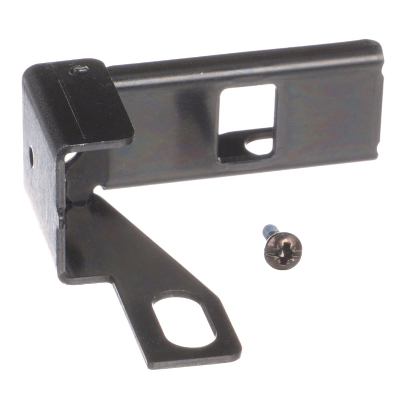
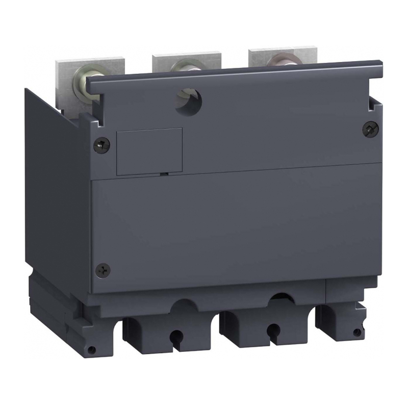
Schneider PowerPact 9422A1 Molded Case Circuit Breaker Accessories
Brand:
Series:
PowerPact
Attachment Name:
Paint flange handle
Model:
9422A1
Order Number:
9422A1
Description:
Schneider Molded Case Circuit Breaker Accessories 9422A1
Product parameters
| Product attributes | Attribute value | Filter product attributes |
|---|---|---|
| Brand: | Schneider | |
| Series: | PowerPact | |
| Attachment Description: | Control attachment, 6 inches, for PowerPact125 | |
| Attachment Type: | - | |
| Attachment Name: | Paint flange handle |
Products with the same attribute : 0
Show details
Series Overview
PowerPact B-Type Molded Case Circuit Breaker Accessories
- Terminal Connections
- Multi-Cable Connector:
- The multi-cable connector is tightened onto the breaker terminals with screws. As a mandatory accessory, it is supplied standard with phase barriers. Alternatively, the extended terminal cover may be used in place of the phase barriers.
- Terminal Extender:
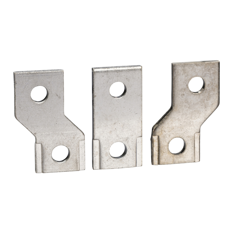
- The terminal extender increases the pole spacing from 27mm (1.063in) to 35mm (1.378in). It includes standard M8 screws, phase barriers, and corresponding nuts and washers.
- Depending on the distance between live non-insulated parts and the grounded metal backplate, the rear insulating barrier may also be required.
- Customer knockout reference: Ø8mm (5/16in).
- Multi-Cable Connector:
- Standard Everlink⁷ Terminal Blocks: Breakers equipped with standard Everlink⁷ terminal blocks allow their terminal connection parts to be removed and replaced with aluminum connectors. These aluminum connectors, made of galvanized aluminum, can connect both copper and aluminum cables.
- Torque-limiting Screws:
- Torque-limiting screws can be used to tighten Everlink⁷ connections, lugs, or busbar connections with the correct torque.
- Insulating Components
- Extended Terminal Cover (IP40):
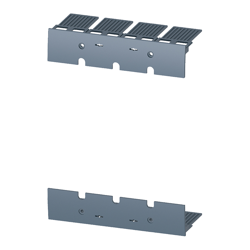
- The extended terminal cover can be installed on the line or load side to prevent direct contact with live parts, meeting IP40 protection class and mechanical impact protection class IK07. Furthermore, it can be installed after the product is mounted on a backplate or DIN rail and can also be used when electrical accessories are wired.
- It is used for front connection of cables or insulated busbars. The cover consists of two parts assembled with screws, achieving IP40 protection.
- The upper part features a sliding grid with knockout markings for precise adaptation to cables or insulated busbars.
- The rear part completely encloses the wiring compartment. Partially removable knockouts can be taken out to accommodate various lugged cables or copper busbar connections.
- Phase Barriers:
- Phase barriers are safety accessories ensuring optimal insulation at connection points.
- They are easily clipped onto the breaker.
- They are not compatible with the extended terminal cover.
- Available in 2 mounting versions: short/long insulation.
- Rear Insulating Barrier:
- The rear insulating barrier is a safety accessory providing insulation at the rear of the device. It must be installed if the distance between conductors and the backplate is less than a specified value and the extended terminal cover is not installed.
- Extended Terminal Cover (IP40):
- Indicating Contacts
- Auxiliary and Alarm Indicating Contacts:
- Universal contacts allow remote indication of breaker status information. They can be used for indication, electrical interlocking, relay control, etc. These contacts are universal changeover type, with Normally Open (NO) and Normally Closed (NC) contacts.
- On/Off - Auxiliary Contact (OF):
- Indicates the position of the breaker contacts.
- Trip Indication - Alarm Contact (SD):
- Indicates breaker tripping due to:
- Electrical fault (overload, short circuit).
- Tripping caused by a shunt trip coil.
- Tripping caused by an undervoltage release coil.
- Pressing the trip button.
- The contact resets after the circuit breaker is reset.
- Indicates breaker tripping due to:
- Auxiliary and Alarm Indicating Contacts:
- Remote Tripping
- Shunt Trip Coil (MX) and Undervoltage Release Coil (MN):
- MX and MN trip coils allow the breaker to be tripped via a control signal. They are primarily used for remote emergency breaking commands. It is recommended to check the system every six months.
- Shunt Trip Coil (MX):
- The breaker trips when the control voltage rises above 70% of its rated voltage (Un).
- Pulse type ≥20ms or maintained signal.
- 110...130VAC shunt trip coils can be used with Class I residual current transformers for earth leakage protection.
- Non-intermittent.
- Undervoltage Release Coil (MN):
- The breaker trips when the control voltage drops below 35% of its rated voltage (Un).
- Tripping is possible between 35% and 70% of the rated voltage.
- It will not trip above 70% of the rated voltage.
- Non-intermittent.
- The breaker can only be closed if the voltage exceeds 85% of the rated voltage. If undervoltage is present, the breaker cannot be closed, whether manually or electrically.
- Time-Delay Unit for Undervoltage Release Coil (MN):
- The time-delay trip unit for the MN coil avoids nuisance tripping due to transient voltage dips (duration ≤200ms). For short interruptions, a delay unit ensures tripping does not occur.
- Shunt Trip Coil (MX) and Undervoltage Release Coil (MN):
- Rotating Handles
- Direct Rotary Handle:
- Installation: Must be mounted on the front cover using 3 screws.
- Operation: Adding the direct rotary handle still guarantees the following functions:
- Suitable for isolation.
- Indicates three positions: O (OFF), I (ON), and "TRIPPED".
- Access to the "TRIP" test button.
- User visibility and setting of the trip unit.
- Equipment Padlocking:
- Standard: With breaker in OFF position, 1~3 padlocks (Ø4~8mm, user-supplied) can be applied.
- With simple modification, it can be locked in ON and OFF positions. When locked in ON, a fault will not prevent tripping. In this case, the handle indicates the TRIPPED position. To move to OFF, unlocking is required.
- Models:
- Standard, with black handle.
- VDE type, with red handle and yellow base, for equipment control.
- Extended Rotary Handle:
- Installation: Consists of:
- Part fixed to the breaker front cover (screwed).
- Component on the cabinet door (handle and cover), always fixed in the same position regardless of vertical or horizontal breaker mounting.
- Extension shaft adjustable in length. Handle mechanism easier to fix using (Ø22 mm) nut assembly. Laser square tool (GVAPL01) for precise door hole/breaker alignment.
- Operation: Allows front operation of breakers mounted inside cabinets. Adding the door handle still guarantees:
- Suitable for isolation.
- Indicates three positions: O (OFF), I (ON), and "TRIPPED".
- User visibility and setting of the trip unit.
- Handle protection class: IP54 or IP65 per IEC 60529.
- Door Interlock:
- A standard feature is a built-in lock in the shaft preventing door opening when the breaker is ON or TRIPPED.
- Can be temporarily disabled with a tool to open the door without opening the breaker. Not possible if the handle is padlocked.
- Equipment and Door Padlocking: Padlocks can lock the breaker handle and disable door opening:
- Standard: With breaker in OFF position, 1~3 padlocks (Ø4~8mm, user-supplied) can be applied.
- For black handles, with simple customer modification during installation, it can be locked in ON and OFF positions. When locked in ON, a fault will not prevent tripping. In this case, the handle indicates TRIPPED. To move to OFF, unlocking is required.
- Operating Breaker with Door Open:
- With an extended rotary handle, a shaft operator for door-open state can be installed on the shaft to operate the breaker with the door open. This accessory complies with UL508.
- Position indication: O (OFF), I (ON), TRIPPED. With door open, the breaker can be padlocked in OFF position.
- Shaft Length: Distance from breaker rear to door:
- Min. shaft length: 200mm.
- Max. shaft length: 600mm.
- Shaft length is adjustable.
- Models:
- Standard, black handle (IP54).
- VDE type, red handle & yellow base (IP54), for equipment control.
- IP65, red handle & yellow base.
- Side rotary handle (left or right).
- Installation: Consists of:
- Side-Mounted Rotary Handle:
- Installation: Consists of:
- Part fixed to the breaker front cover.
- Component mounted on the cabinet side (left or right) (handle and cover).
- Adjustable extension shaft.
- IP54 handle mechanism.
- IP65 handle mechanism.
- Easier assembly using (Ø22mm) nut for handle mechanism.
- Operation: Allows side operation of breakers mounted inside cabinets. Adding the side handle guarantees:
- Suitable for isolation.
- Indicates three positions: O (OFF), I (ON), and "TRIPPED".
- User visibility and setting of the trip unit.
- Handle protection class: IP54 or IP65 per IEC 60529.
- Equipment Padlocking:
- For black handles, with simple customer modification during installation, it can be locked in ON and OFF positions. When locked in ON, a fault will not prevent tripping. Standard: With breaker in OFF position, 1~3 padlocks (Ø4~8mm, user-supplied) can be applied. When locked in ON, a fault will not prevent tripping. In this case, the handle indicates TRIPPED. To move to OFF, unlocking is required.
- Shaft Length: Distance from breaker rear to door:
- Min. shaft length: 45mm.
- Max. shaft length: 480mm.
- Shaft length is adjustable.
- Models:
- Standard, black handle (IP54).
- VDE type, red handle & yellow base (IP54), for equipment control.
- IP65, red handle & yellow base (Order 1 standard type and 1 IP65 universal handle).
- Installation: Consists of:
- Direct Rotary Handle:
- Locking and Sealing Accessories
- Lock:
- Locks the breaker in the OFF position, ensuring isolation requirements per IEC 60947-2 are met. Up to three padlocks (Ø5~8mm, user-supplied) can be fitted. Some locking devices require additional accessories.
- Sealing Accessories:
- Sealing accessories are provided. Each pack contains all parts needed for various seals. The pack includes:
- 6 sealing accessories.
- 6 sealing blocks.
- Sealing accessories are provided. Each pack contains all parts needed for various seals. The pack includes:
- Lock:
PowerPact H, J, L Type Molded Case Circuit Breaker Accessories
- 4 Indicating Contacts:
- 2 N/OFF (Auxiliary Contacts [OF1 and OF2]).
- 1 Trip Indication Contact [SD].
- 1 Fault Indication Contact [SDE].
- One Remote Trip Coil:
- One Undervoltage Coil (MN).
- Or one Shunt Trip Coil (MX).
- Indication and Alarm Contacts
- Auxiliary and Alarm Indicating Contacts:
- Application:
- Open/Closed Status Indication (OF): Indicates the position of the breaker contacts.
- Trip Alarm Indication (SD): Indicates breaker tripping due to short circuit, overload, earth fault, or tripping caused by undervoltage/shunt trip coils. Resets when the breaker is reset.
- Fault Indication Contact (SDE): Indicates breaker tripping due to a fault: overload, short circuit, earth fault. Resets when the breaker is reset.
- Rotary Handle Indication: CAO (Pre-open) and CAF (Pre-close): Installed inside the rotary handle.
- Installation and Connection:
- OF/SD/SDE can be clipped into slots under the breaker front cover.
- Different contact types look identical; their function depends on their position within the breaker.
- SDE requires an operator to function.
- Application:
- Auxiliary and Alarm Indicating Contacts:
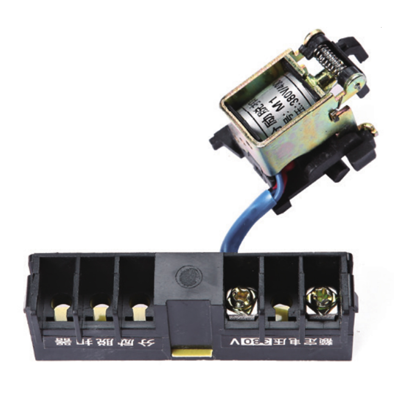
- Shunt Trip Coil (MX) and Undervoltage Coil (MN):
- Allows the breaker to be opened via a loss of voltage signal.
- Shunt Trip Coil and Undervoltage Coil:
- Application:
- Shunt Trip Coil (MX): Trips the breaker when voltage rises to ≥70% of rated voltage. Opens the breaker via pulse (≥20ms) or maintained signal. For AC shunt trip coils, used with a Class I earth leakage CT for earth fault protection.
- Undervoltage Coil (MN): Trips the breaker when the supply voltage drops below the set value. Trips between 35% and 70% of rated voltage. The breaker can be closed when the trip coil voltage U ≥ 80% Un. When the coil is de-energized, the breaker cannot be closed, either electrically or manually.
- Installation and Connection:
- Coil accessories are installed in slots under the breaker front cover.
- Each requires wiring with 18-14 AWG (1.0-2.5mm²) copper wire.
- Operation:
- After MX or MN trips the breaker, it must be reset before closing.
- MX and MN trip commands have priority over manual closing; if a trip command persists, the breaker cannot be closed (even temporarily).
- Application:
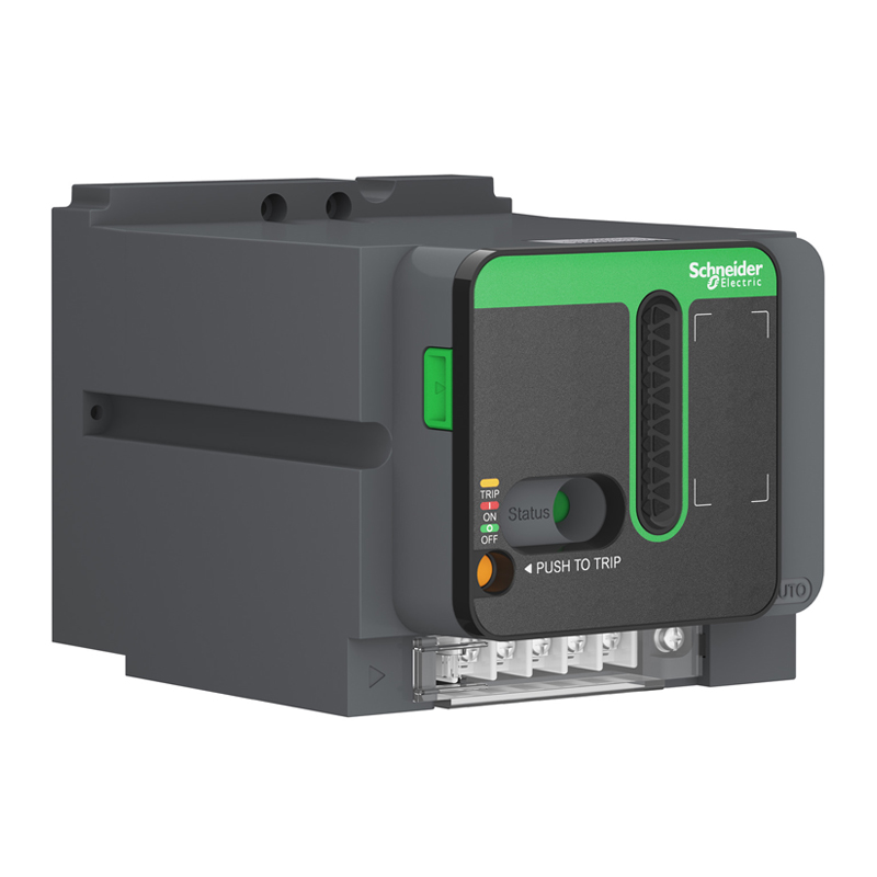
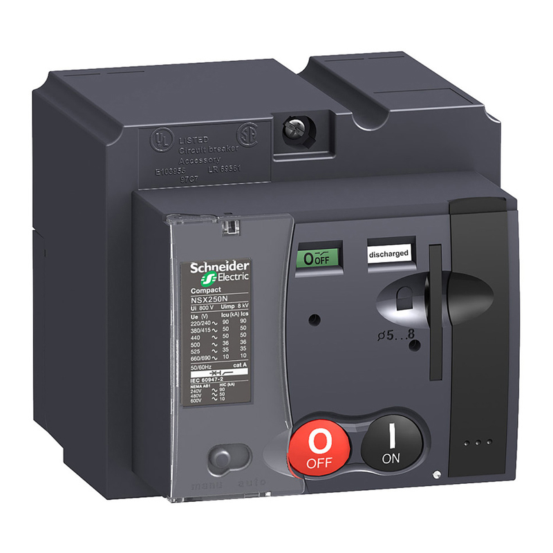
- Motor Operator:
- Using a motor operator module provides the breaker with higher mechanical endurance and ease of operation:
- All breaker information remains clearly visible, including trip unit data.
- Isolation function with padlocking capability.
- Double insulation barrier.
- Application:
- Local electrical operation, centralized operation, automatic control.
- Mains/standby power transfer, or switching to alternative sources to optimize energy costs.
- Load shedding and reconnection.
- Synchronous coupling.
- Installation and Connection:
- Suitable for H and J frame breakers.
- Terminals behind the motor module front cover are used for connection.
- Wiring capacity: 14 AWG (2.5mm²).
- Automatic Operation:
- Switching open/close controlled by two pulse or maintained signals.
- Spring automatically charges after tripping by MN or MX coil.
- Manual reset required after electrical fault trip.
- Manual Operation:
- Controlled by ON, OFF buttons.
- Press the charging handle nine times to charge the mechanism.
- Can be padlocked in the OFF position.
- Using a motor operator module provides the breaker with higher mechanical endurance and ease of operation:

Rachel
Industrial Control Sales Specialist: Focuses on delivering high-performance, cost-effective industrial control products. Offers end-to-end one-stop procurement support—covering rapid quotation, streamlined order fulfillment, and responsive after-sales service—to simplify clients’ procurement processes.
Email: Anthony@icxsg.com
We offer competitive product pricing. For fast support, send your email, phone, address, and the product model & quantity you want—we’ll reach out quickly!
We typically respond via email within one business day! You can also contact us at Anthony@icxsg.com