ComPacT NSX Accessories - Outline
Fixed Circuit Breakers
Fixed circuit breakers can be connected directly to busbars or via cable lugs. Bare cable connectors are also available for bare copper or aluminum cables.
ComPacT NSX circuit breakers can be installed horizontally or vertically, flush or top-mounted, without affecting performance. There are three mounting methods:
● Fixed
● Plug-in
● Withdrawable
The latter two methods require adding corresponding accessories (bases, side plates, etc.) to the fixed version. Many connection accessories are common to all three methods.
Plug-in Circuit Breakers
● Using plug-in circuit breakers allows:
● Withdrawing or quickly replacing the circuit breaker without touching the incoming/outgoing wiring or the mounting base.
● Pre-installing plug-in bases for easy future addition of circuit breakers.
● Isolating the power circuit when the base is flush-mounted or panel-mounted. Comprehensive insulation is achieved using short terminal shields (mandatory) on the device. Protection ratings are:
● Breaker plugged in = IP4X
● Breaker withdrawn = IP2X
● Breaker withdrawn, base with shutters = IP4X
● Plug-in Circuit Breaker Configuration
● Plug-in configuration is achieved by adding a "plug-in kit" to a fixed circuit breaker. To avoid connecting or disconnecting under load, a safety trip device automatically trips the breaker if it is in the ON state before insertion or withdrawal from the base. This safety trip device is included in the plug-in kit and must be installed on the breaker.
● Accessories
● Optional insulation accessories:
● Terminal shields to prevent direct contact with terminals.
● Phase barriers to enhance insulation between phases.
Withdrawable Circuit Breakers
● Withdrawable circuit breakers offer all the advantages of plug-in types and are very easy to operate. They have three positions:
● Connected position: Power circuit connected.
● Withdrawn position: Power circuit disconnected; the breaker can be operated to check auxiliary circuits.
● Breaker removed: The breaker can be taken off the base.
● Withdrawable Circuit Breaker Configuration
● In withdrawable configuration, two side plates need to be installed on both the base and the circuit breaker. Similar to plug-in configuration, a safety trip device automatically trips the breaker if it is in the ON state during insertion or withdrawal, ensuring operation in the "OFF" position.
● Accessories
● The base used is the same as for plug-in. Additionally:
● Rack auxiliary contacts indicate the breaker's "Connected" and "Withdrawn" positions.
● Locking with 1 to 3 padlocks (diameter 5 to 8mm) enables:
● Preventing breaker insertion.
● Locking the breaker in the "Connected" or "Withdrawn" position.
● A toggle switch cover ensures a suitable protection rating regardless of the breaker's position.
● A telescopic shaft for extending the rotary handle allows the door to be closed when the equipment is in the "Connected" or "Withdrawn" position.
Wiring for Fixed Circuit Breakers
Front Wiring
Busbars or cables with lugs.
Standard Terminals
ComPacT NSX100-630 terminals include nuts and screws:
● ComPacT NSX100: M6 nuts and screws.
● ComPacT NSX160/250: M8 nuts and screws.
● ComPacT NSX400/630: M10 nuts and screws.
● These terminals can be used for:
● Direct connection of insulated busbars or cables with lugs.
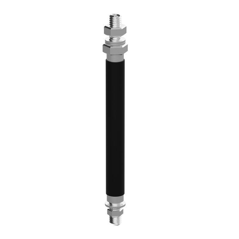
● Terminal extensions providing more wiring options.
● Phase barriers or terminal shields are recommended. Certain connection accessories require these components (phase barriers are provided in such cases).
● Busbars
● If non-insulated busbars are used for connection, full type testing of the switchboard is required to confirm the configuration.
● Lugs
● Lugs are available for both aluminum and copper cables. Lugs must comply with connection regulations. They must be used with phase barriers or long terminal shields.
● Terminal Extenders
● Terminal extenders connect to the standard terminals of the breaker, providing multiple wiring schemes in a compact space:
● Straight terminal extender
● Right-angle terminal extender
● Corner terminal extender
● Double U-type terminal extender
● 45° angle terminal extender
● Pole Spacing Extenders
● Pole spacing can be increased using pole spacing extenders:
● NSX100/160/250: Pole spacing increases from 35mm to 45mm.
● NSX400/630: Pole spacing increases from 45mm to 52mm or 70mm.
● Busbars, lugs, or terminal extenders can be connected to the line or load side of the breaker.
● Integrated Extenders for NSX100/160/250
● Integrated extenders enable:
● Increasing the 35mm pole spacing of NSX100/160/250 breaker terminals to match the 45mm spacing of NSX400/630.
● Using all connection and insulation accessories available for the next larger frame size (lugs, cable connectors, terminal extenders, terminal shields, phase barriers).
● Compatibility with Interpact INS disconnectors.
● ComPacT NSX devices with integrated extenders can be installed:
● At the rear of the switchboard.
● On a panel using spacers.
● Integrated extenders also:
● Align breakers of different frame sizes within a switchboard.
● Allow the use of identical mounting bases regardless of current rating.
Wiring for Fixed Circuit Breakers - Bare Cables
Bare copper and aluminum cables (without lugs) can be connected using bare cable connectors.
● Single Cable Connectors for ComPacT NSX100/160/250
● Connectors clip onto the breaker terminals or are secured via fixtures onto straight terminal extenders, right-angle terminal extenders, or pole spacing extenders.
● Single Cable Connectors for ComPacT NSX400/630
● Connectors are screwed onto the breaker terminals.
● Double Cable Connectors for ComPacT NSX100/160/250 & 400/630
● Connectors are screwed onto breaker terminals or right-angle terminal extenders, etc.
Rear Connection Terminals
● Breakers mounted on backplates can be wired behind the mounting panel using rear connection terminals.
● Busbars or Cable Lugs
● Rear connection terminals for busbars or cables with lugs come in two lengths. They offer four connection positions.
● Rear connection terminals easily secure onto the breaker's connection terminals. All combinations of rear connection lengths and positions are achievable.
● Bare Cables
● For rear connection with bare cables, single cable connectors for ComPacT NSX100/160/250 can be securely fixed to the rear connection terminal using a clamp.
Wiring for Withdrawable and Plug-in Circuit Breakers
Busbars or Cables with Lugs
● Plug-in bases feature connection terminals usable for front or rear wiring.
● For rear wiring with plug-in bases mounted on panels, the terminals must be replaced with long right-angle terminal extenders.
● For ComPacT NSX630, 52.5mm or 70mm pole spacing extenders are typically required for connection.
● Connection Accessories
● All accessories for fixed breakers (busbars, connectors, terminal extenders, pole spacing extenders) can be used with plug-in bases.
● Bare Cables
● All terminals can be equipped with bare cable connectors.
● Adapters for Plug-in Bases
● An adapter is a plastic component used for 100/160/250 and 400/630 plug-in bases, enabling the use of all wiring accessories designed for fixed breakers (e.g., phase barriers and long/short terminal shields require this adapter).
Insulation of Live Parts
Terminal shields for fixed and plug-in/withdrawable breakers are identical and suitable for all applications up to 690V. Rated for current ranges 100/160/250A and 400/630A, available in long and short versions.
● Terminal Shields
● Terminal shields are insulating accessories preventing direct contact with the power circuit. They meet IP40 protection and IK07 mechanical impact protection.
● Types of Terminal Shields
● For ComPacT NSX100/160/250 and NSX400/630 3P or 4P:
● Short terminal shield
● Long terminal shield
● Short Terminal Shield
● Short terminal shields can be used for:
● All plug-in and withdrawable breakers.
● Fixed breakers with rear connections.
● Long Terminal Shield
● Long terminal shields are used for front connection of cables or insulated busbars.
● Long terminal shields consist of two parts assembled with screws, achieving IP40 protection.
● The upper part has sliding shutters with separation markings for precise cable or insulated busbar matching.
● The rear part completely encloses the connection area. Locally removable fingers allow adaptation for various lugged cables or copper busbar connections.
● Long terminal shields can be installed on the line or load side of:
● Fixed breakers.
● Bases of plug-in and withdrawable breakers. This, combined with the mandatory short terminal shield on the breaker, provides enhanced insulation.
● Integrated extenders for NSX100/160/250.
● 52.5mm extenders for NSX400/630.
● Phase Barriers
● Phase barriers are safety accessories ensuring more reliable insulation at connection points:
● Easily installed by clipping onto the breaker.
● Only one type. Installed on fixed breakers or plug-in base adapters.
● Not compatible with terminal shields.
● Require an adapter on the base for installation on plug-in/withdrawable breakers.
● Rear Insulation Barrier
● The rear insulation barrier is a safety accessory providing insulation at the rear of the device.
● It is mandatory for breakers mounted on panels with extenders if terminal shields are not used.
Electrical Accessory Connections
Standard
● All ComPacT NSX100/160/250 breakers and disconnectors have internal space for installing:
● 5 auxiliary contacts:
● 2 ON/OFF auxiliary contacts (OF1 and OF2)
● 1 trip indication contact (SD)
● 1 fault trip indication contact (SDE)
● 1 earth leakage fault contact (SDV) (when equipped with an earth leakage module)
● 1 remote trip coil
● 1 MN undervoltage release coil or 1 MX shunt trip coil
● Remote Indication
● Breakers with MicroLogic trip units can identify fault types via indication contacts or the SDTAM module:
● With two outputs:
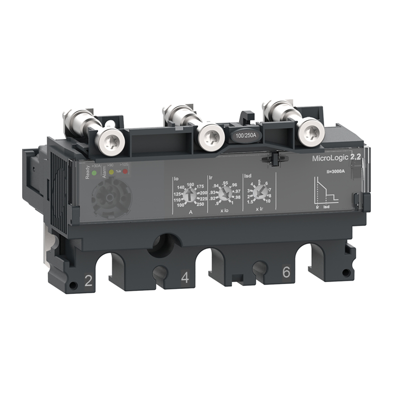
● SDx module used with MicroLogic 2.2/4.2/5.2B/5.2A/5.2E/6.2A/6.2E or 7E, or
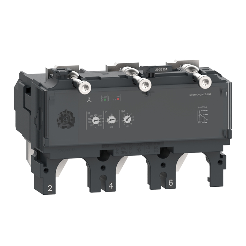
● SDTAM module used with MicroLogic 2.2 M or 6-2 E-M (motor protection). This module occupies one OF contact slot and one MN/MX trip coil slot. All these accessories are installed inside the breaker. Installation is unaffected by adding motor operators or rotary handles.
● Communication: Modbus SL Protocol
● Communication functions require dedicated accessories.
● Telemetry (Status)
● 1 DCM communication module (provides OF, SDE status)
● 1 LV434210 (provides SD status)
● Telemetry & Telecontrol (Status & Control)
● 1 DCM communication module (provides OF, SDE status)
● 1 LV434210 (provides SD status)
● 1 motor operator with communication function (connected to DCM module)
● Telemetry & Teleadjustment (Measurement & Setting)
● 1 DCM communication module for communication and providing 24V DC power to MicroLogic
● 1 MicroLogic 5/6/7 A/E electronic trip unit (connected to DCM module)
● Four Functions (Status, Control, Measurement, Setting)
● 1 DCM communication module (provides OF, SDE status)
● 1 LV434210 (provides SD status)
● 1 motor operator with communication function (connected to DCM module)
● 1 MicroLogic 5/6/7 A/E electronic trip unit (connected to DCM module)
● Installation of SDx or SDTAM is compatible with communication functions.
● Communication: ULP or Modbus SL Protocol
● Communication functions require dedicated accessories.
● BSCM Modbus SL/ULP can operate in modes:
● Modbus SL mode
● Modbus SL and ULP mode
● ULP mode
● Telemetry (Status)
● Modbus SL interface: Requires 1 BSCM Modbus SL/ULP module, 1 BSCM SL cable, 1 Modbus SL hub (connects up to 3 BSCM Modbus SL/ULP modules).
● ULP interface: Requires 1 BSCM Modbus SL/ULP module, 1 NSX cable, and 24V DC power. Insulated NSX cable mandatory if system voltage exceeds 480V AC.
● Telemetry function compatible with toggle or rotary handles.
● Telemetry & Telecontrol (Status & Control)
● In addition to above accessories, requires:
● 1 motor operator with communication function connected to BSCM and LV434210 for SD status indication.
● Telemetry (Measurement)
● MicroLogic 5/6/7 A/E provides this function. System includes:
● Modbus SL interface: 1 BSCM module, 1 Modbus SL cable, 1 Modbus hub for communication between trip unit and gateway/SCADA.
● ULP interface: 1 NSX cable (including internal terminal block) for communication and providing 24V DC power to MicroLogic.
● Telemetry function compatible with standard or communication motor operators and rotary handles.
● Four Functions (Status, Control, Measurement, Setting)
● MicroLogic 5/6/7 A/E provides this function. System includes:
● Modbus SL interface: 1 BSCM module, 1 Modbus SL cable, 1 Modbus hub for communication between trip unit and gateway/SCADA.
● ULP interface: 1 NSX cable (including internal terminal block) for communication and providing 24V DC power to MicroLogic.
● 1 motor operator with communication function connected to BSCM.
● Installation of SDx or SDTAM is compatible with communication functions.
Accessory Selection
Standard
● NSX400/630 breakers and disconnectors have internal space for installing:
● 7 auxiliary contacts:
● 4 ON/OFF auxiliary contacts (OF1, OF2, OF3, OF4)
● 1 trip indication contact (SD)
● 1 fault trip indication contact (SDE)
● 1 earth leakage fault contact (SDV) (when equipped with a module)
● 1 remote trip coil
● 1 MN undervoltage release coil or 1 MX shunt trip coil
● Remote Indication
● Breakers with MicroLogic trip units can identify fault types via indication contacts or SDTAM module:
● With two outputs:
● SDx module used with MicroLogic 2.3/4.3/5.3B/5.3A/5.3E/6.3A/6.3E or 7E, or
● SDTAM module used with MicroLogic 2.3M or 6-3E-M (motor protection).
● This module occupies one MN/MX trip coil position. All these accessories are installed inside the breaker. Installation is unaffected by adding motor operators or rotary handles.
● Communication: Modbus SL Protocol (Identical description to NSX100-250 section applies for NSX400-630)
●
Communication: ULP or Modbus SL Protocol (Identical description to NSX100-250 section applies for NSX400-630)
Electrical Accessory Connections
Fixed ComPacT NSX
Secondary circuits exit the breaker via openings in the front cover.
Plug-in/Withdrawable ComPacT NSX
Automatic 9-Wire Connectors
Secondary circuits are routed out via 1-3 automatic 9-wire connectors (9 wires each). Connections can be disconnected when the breaker is withdrawn. Includes:
● Mobile part, attached to the breaker via a bracket (one bracket per breaker).
● Fixed part, mounted on the plug-in base, with connectors for bare cables up to 2.5mm² cross-section.
● Automatic 9-Wire Connector Selection
● Depending on installed accessories, 1 to 3 connectors may be required.
Withdrawable ComPacT NSX
Manual 9-Wire Connectors
Withdrawable breakers can be equipped with 1-3 manual 9-wire connectors (9 wires each). Secondary circuits remain connected when the breaker is in the "Withdrawn" position, allowing testing via breaker operation.
Indication Contact Functions & Characteristics
Function
Indicate breaker status during normal operation or after a fault. A universal contact type provides different functions depending on its installation location:
● OF (ON/OFF): Indicates main contact position.
● SD (Trip Indication): Indicates tripping due to:
● Overload
● Short circuit
● Earth fault / Earth leakage fault
● Tripping by voltage release coil
● Pressing the trip button
● Removing the breaker from a plug-in/withdrawable base while ON.
● Resets after breaker reset.
● SDE (Fault Trip Indication): Indicates tripping due to:
● Overload
● Short circuit
● Earth fault / Earth leakage fault
● Resets after breaker reset.
● SDV (Earth Leakage Fault Trip Indication): Indicates tripping due to earth leakage fault. Resets after module reset.
● Low-level versions of these contacts are available for switching weak loads (e.g., PLCs or electronic circuits).
● Rotary Handle Position Contact for Pre-close/Pre-open Indication
● CAM (Pre-close/Pre-open function): Indicates rotary handle position. Opens (pre-open) before the breaker opens, or closes (pre-close) before the breaker closes.
● Withdrawable Position Contacts
● CE/CD (Connected/Disconnected): Microswitches for withdrawable breakers.
● Installation
● OF, SD, SDE, SDV functions: Universal contact type (function depends on location). Contacts clip into slots behind the front cover (or in the module for SDV).
● SDE adapter required for SDE function on breakers with TM, MA, MIC2.2, MIC5.2B trip units.
● CAM function: Contact installed in the rotary handle (direct or extended).
● CE/CD function: Contacts clip onto the fixed part of the withdrawable kit.
● Wireless Auxiliary & Alarm Indication Contacts
● Wireless communication digital module for ComPacT NSX 100-630 frame MCCBs. Simple installation enables digital upgrade. Uses Zigbee protocol. Installed in different locations to provide OF/SD/SDE/SDV status indications.
Pre-wired Standard Auxiliary Contact Functions & Characteristics
Pre-wired standard auxiliary contacts provide remote indication of breaker status information. Compliant with GB14048.5 standard.
● Installed in different locations to provide OF, SD, SDE, SDV functions.
● Each contact has two isolated contact circuits for different secondary voltages. Each circuit has max. 1 NO, 1 NC, 1 common terminal (refer to wiring diagram).
● Pre-wired with 1m low-smoke, halogen-free, flame-retardant cable.
● Optional cable sizes, quantities, and contact configurations:
● 1mm², 6 wires: 2 NO, 2 NC
● 1mm², 4 wires: 1 NO, 1 NC
● 1mm², 4 wires: 2 NO
● 1mm², 4 wires: 2 NC
● 0.5mm², 6 wires: 2 NO, 2 NC
● 0.5mm², 4 wires: 1 NO, 1 NC
● 0.5mm², 4 wires: 2 NO
● 0.5mm², 4 wires: 2 NC
SDx and SDTAM Modules for MicroLogic
● SDx and SDTAM are indication contacts with two static outputs signaling different fault types. They cannot be used simultaneously.
● SDx Indication Contact
● SDx module remotely indicates trip or alarm conditions for ComPacT NSX breakers with electronic trip units.
● All MicroLogic units have SD2 output indicating overload function.
● MicroLogic 5/6 have SD4 output assignable to:
● Overload pre-alarm (MicroLogic 5)
● Earth fault trip indication (MicroLogic 6)
● Both outputs reset automatically when the switch closes.
● For MicroLogic 5/6, SD2 and SD4 outputs can be reprogrammed to other trip or alarm functions.
● Output Characteristics
● Functions assignable:
● Latching for a delay period, returning to initial state after delay.
● Permanent latching. Requires communication function to reset.
● Static output: 24 to 415V AC/DC; max. 80 mA.
● SDTAM Indication Contact
● SDTAM module is dedicated to motor protection MicroLogic trip units 2.2M, 2.3M, 6.2E-M, 6.3E-M. It connects to the contactor, opening it 400ms before the breaker trips in case of overload or other motor faults, avoiding breaker opening.
● MicroLogic 2M
● SD4 output opens contactor before normal breaker opening (400ms) for: Overload, Phase imbalance or loss.
● SD2 output records contactor opening via SDTAM.
● MicroLogic 6E-M
● SD4 output opens contactor before normal breaker opening (400ms) for: Overload, Phase imbalance or loss, Locked rotor, Underload, Long start.
● SD2 output records contactor opening via SDTAM.
● Output Characteristics
● Reset via:
● Manual reset via button in wiring diagram.
● Automatic reset after delay (configurable 1-15 min), considering motor cooling time.
● Static output: 24 to 415V AC/DC; max. 80 mA.
Motor Operator Functions & Characteristics
● Using a motor operator module gives ComPacT NSX breakers high mechanical endurance and convenient, reliable operation:
● All breaker indication functions and information remain visible, including trip unit settings and indications.
● Isolation function with padlocking capability.
● Double insulation for panel mounting.
● A dedicated motor operator with communication function is required for operation via communication. It must connect to a BSCM module to receive open/close commands. Operation is identical to the standard motor operator.
● Applications
● Local motor operation, centralized control, automatic control.
● Mains/standby source transfer, or switching to optimize energy costs.
● Load shedding and reconnection.
● Synchronous coupling.
● Operation
● Operation type selected via manual/auto selector switch (7), sealable with a transparent cover.
● Auto Operation: Switch in "Auto" position locks ON/OFF (I/O) buttons and manual charging mechanism. Switching controlled by two pulse or maintained signals. Spring auto-charges after MN or MX coil trip. Manual reset required after electrical fault trip.
● Manual Operation: Switch in "Manual" position enables ON/OFF buttons. Microswitch indicates manual position remotely. Control via "ON, OFF" buttons. Press charging handle nine times to charge mechanism. Lockable in OFF position.
● Installation & Connection
● Compatible with all mounting (fixed, plug-in, withdrawable) and connection methods. Terminals behind motor operator front cover accept wires up to 2.5mm².
● Optional Accessories
● OFF position padlock.
● Operation counter for ComPacT NSX400/630, indicating ON/OFF operations, mounted on motor operator front.
Universal Motor Operator Functions & Characteristics
● Controls breaker open/close operations:
● Remote control via electrical signal.
● Direct local control via manual operator on breaker front panel.
● Operation
● Operation type selected via manual/auto sliding cover (3).
● Auto Operation: Selector in AUTO position allows remote closing/opening via electrical pulse or maintained signal.
● Manual Operation: Selector in MANU position allows manual open/close via handle within motor operator slider, accessible at the front.
● Installation & Connection
● Compatible with all mounting (fixed, plug-in, withdrawable) and connection methods.
● Terminals behind motor operator front cover accept wires up to 2.5mm².
Remote Trip Functions & Characteristics
● MX or MN voltage release coils trip the breaker, primarily for remote emergency stop commands. System check recommended every six months.
● MN Undervoltage Release Coil
● Opens breaker when supply voltage drops below 35% of rated voltage Un. Combined with an emergency stop button, enables fail-safe tripping. MN coil continuously energized. Power interruption due to:
● Active disconnection via emergency stop button.
● Power loss or wiring fault.
...causes coil to open breaker.
● Activation Conditions (IEC 60947-2 compliant):
● Trip certain when U ≤ 0.35 x Un.
● Trip possible when U between 0.35 and 0.7 Un.
● No trip certain when U > 0.7 Un.
● Reset Conditions:
● Breaker cannot close (manually or electrically) while MN coil is de-energized. Closing certain when U ≥ 0.85 x Un. Not guaranteed below this threshold.
● MN Release Coil Time Delay Unit
● Avoids nuisance tripping due to short voltage dips (duration ≤ 200ms) by introducing a delay
MX Shunt Trip Coil
● MX trip coil automatically opens the breaker when energized by a pulse-type (≥20 ms) or maintained signal.
● Activation Conditions:
● Trip certain when voltage U ≥ 0.7 × Un.
Controlling the Breaker via MN or MX
● After tripping by MN or MX, the breaker must be reset before it can be closed.
● MN or MX trip has priority over manual closing.
● If a trip command persists, the breaker cannot close (even temporarily).
● Use connection wires ≤1.5mm² with terminals.
Rotary Handle Functions & Characteristics
Direct Rotary Handle
Standard Handle
Protection rating IP40, IK07. Adding maintains:
● User visibility/settability of trip unit.
● Suitability for isolation.
● Three-position indication: 0 (OFF), I (ON), "Trip".
● Access to "trip" test button.
Locking
● Padlocking:
● Standard: Lock in OFF position with 1–3 padlocks (Ø5–8mm, user-supplied).
● Modified: Lock in ON/OFF positions. When locked ON, faults still trip breaker (handle shows "Trip"). Unlock to return to OFF.
● Key Lock: Optional Ronis/Profalux lock on handle base provides similar functionality.
Pre-close/Pre-open Contacts (Optional)
● Enable:
● Powering MN coil before breaker closes.
● Opening contactor control before breaker opens.
MCC Switchgear Control Kit
● Adds:
● Higher IP rating: IP43, IK07 (increasable via gasket).
● Door interlock:
● Door open → Breaker cannot close.
● Breaker ON/tripped → Door cannot open.
● Tool temporarily disables interlock (impossible if handle padlocked).
CNOMO-Compliant Machine Tool Kit
● Adds:
● Enhanced protection: IP54, IK08.
● Compliance with CNOMO E03.81.501N.
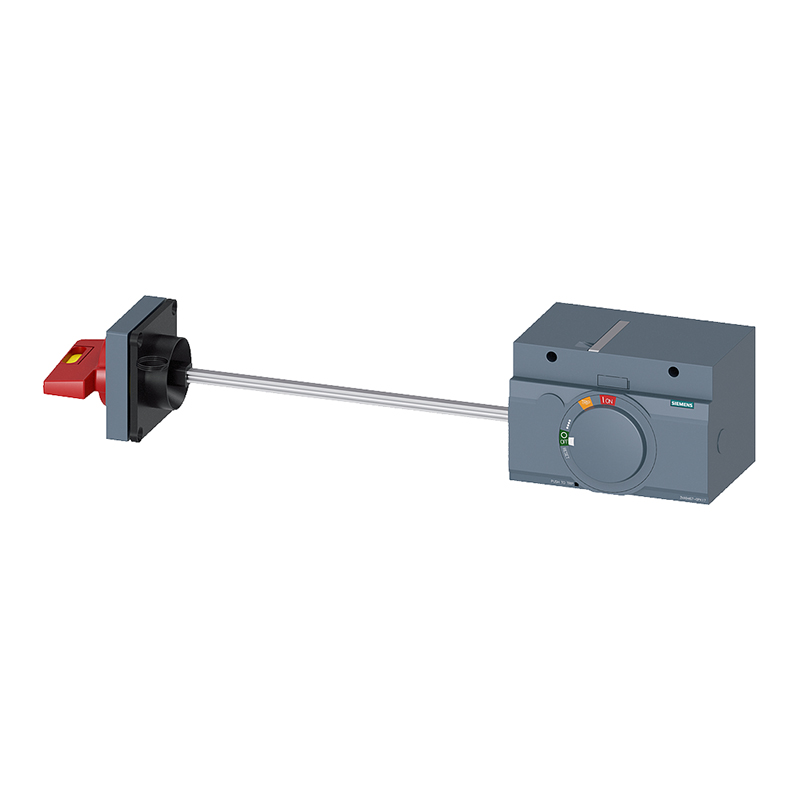
Extended Rotary Handle
● Protection IP55, IK08. Operates breaker from switchgear door. Maintains:
● Trip unit visibility/settability.
● Isolation suitability.
● Three-position indication.
Door Interlock
● Standard: Locks door when breaker ON/tripped.
● Tool temporarily disables interlock (impossible if padlocked).
● Active Interlock Cancellation: Reversible on-site modification disables interlock (even with padlocks).
Locking
● Padlocking:
● Standard: Lock in OFF position (1–3 padlocks, Ø5–8mm).
● Modified: Lock in ON/OFF positions (faults trip breaker; unlock to reset).
● Key Lock: Optional Ronis/Profalux lock on handle base.
Accessory for Door-Open Operation
● Allows breaker operation with door open.
● Padlockable in OFF position.
Components
● Breaker-mounted part (replaces front cover).
● Door-mounted handle/nameplate (fixed position).
● Adjustable shaft length (min/max distance to door):
● NSX100–250: 171–600 mm
● NSX400/630: 195–600 mm
● Withdrawable Breakers: Telescopic shaft for "withdrawn" position:
● NSX100–250: 248–600 mm
● NSX400/630: 272–600 mm
Manual Power Transfer System
● Interlock accessory for two rotary-handle breakers.
● Only one breaker closable at a time.
● Padlockable in ON/OFF positions (max 3 padlocks).
Mechanical Interlocks
For Toggle Handles (2–3 Devices)
● System:
● Two-device interlock; extendable to three devices.
● Allowed positions: One ON (others OFF) or all OFF.
● Lockable with 1–2 padlocks (Ø5–8mm).
● Compatibility:
● Types: For INS/INV, NSX100–250, NSX400–630.
● Devices: Fixed/plug-in NSX100–630 breakers/disconnectors (same size/handle type).
For Rotary Handles (2 Devices)
● System: Padlocks added to handles.
● Allowed positions: One ON (other OFF) or both OFF.
● Lockable with ≤3 padlocks (Ø5–8mm).
●
Compatibility: Same as toggle-handle interlock.
Key Interlocking (Multiple Devices)
● System:
● Identical lock cores on devices. Single key: Remove from one device to close another.
● Enables interlocking distant/dissimilar devices (e.g., MV/LV, NSX100/NSX630).
●
Compatibility: All rotary-handle NSX100–630 devices; interoperable with other key-lock equipment.
Base Interlock (2 Devices)
● System:
● Dedicated base for horizontal/vertical mounting.
● Rear mechanism interlocks without affecting controls.
● Compatibility:
● All fixed/plug-in NSX100–630 breakers/disconnectors (rotary/toggle handles).
● Adapter Kits Required For:
● Two plug-in devices.
● NSX100–250 + NSX400–630 devices.
● Busbar accessories enable easy outgoing connections.
Additional Measurement/Indication Modules
Current Transformer (CT) Module
● Connects to ammeters/power meters.
● Installation:
● Mounts on load-side terminals.
● IP40, IK04. Class insulation.
● Terminals for ≤2.5mm² cables.
● Specs:
● CT secondary: 5A.
● Output (Class 3):
│ Rating │ Consumption │
│ 100A │ 1.6 VA │
│ 150A │ 3 VA │
│ 250A │ 5 VA │
│ 400/600A │ 8 VA │
CT Module with Voltage Outputs
● Connects to digital meters (e.g., PM700/800).
● Installation: Same as CT module.
● Specs:
● Ue: 530V; 50–60Hz.
● CT secondary: 5A. Accuracy:
│ Rating │ Class │ Consumption │
│ 125/150/250A │ 1 │ 1.1 VA │
│ 400/600A │ 0.5 │ 2 VA │
● Voltage outputs: 4 channels, 3500Ω±25% impedance, 1mA max current (measurement only).
Locks & Sealing
Locks
● Lock in OFF position (IEC 60947-2 compliance) with ≤3 padlocks (Ø5–8mm). Some locks require accessories.
Sealing Accessories
● Circuit Identification: Label clips (Ref: LV429226; 10/pack), panel-frame compatible.
● Seal Kits: Include:
● 6 sealing accessories + blocks.
● 0.5m wire + 2 screws.
Panel Frames & Covers
For Fixed Breakers
● IP30: Adhesive-mounted frames (3 types):
│ Type │ Function │
│ Universal │ All controls │
│ No trip unit access │ – │
│ Trip unit access │ – │
│ Vigi module │ Compatible with above │
●
IP40: Screw-mounted frames with gasket (4 types; includes wide frame for Vigi/ammeter modules).
For Withdrawable Breakers
● IP40 Frames:
│ Control Type │ Components │
│ Rotary/motor operator │ Standard IP40 frame │
│ Extended toggle │ Frame + protective cover │
●
Vigi Module: Same as above.
IP43 Toggle Handle Cover
● For toggle handles only. IP43, IK07. Installed on breaker front.
Adapted Front Covers
● Allow NSX installation in NS switchgear:
● NS100–250 front cover.
● NS400/630 front cover.








 English
 Français
 Deutsch
 Português
 Español
 русский
  한국어
한국어 العربية
 Italiano
 Indonesia
 Schweiz
 Polski
 Nederlands
 ישראל - עברית
 Perzisch
 ไทย
ไทย 日本語
日本語 ኢትዮ-አማርኛ
 Việt Nam
 Kiswahili
 Srpski
 Ελληνικά
 简体中文
简体中文