







 English
 Français
 Deutsch
 Português
 Español
 русский
  한국어
한국어 العربية
 Italiano
 Indonesia
 Schweiz
 Polski
 Nederlands
 ישראל - עברית
 Perzisch
 ไทย
ไทย 日本語
日本語 ኢትዮ-አማርኛ
 Việt Nam
 Kiswahili
 Srpski
 Ελληνικά
 简体中文
简体中文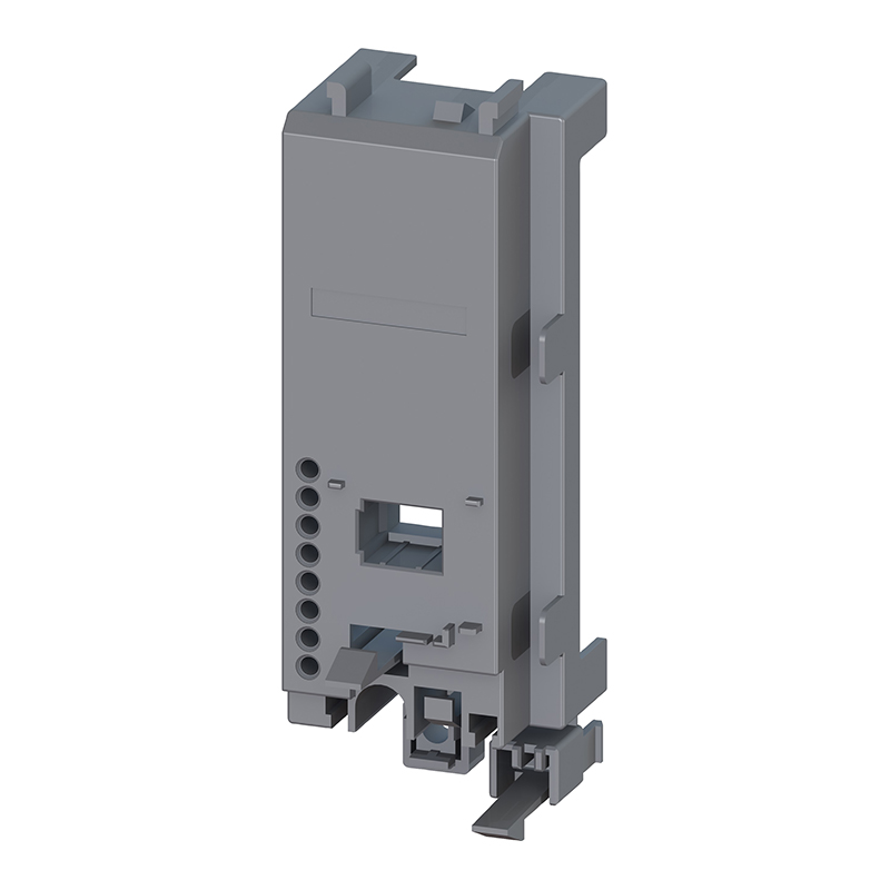
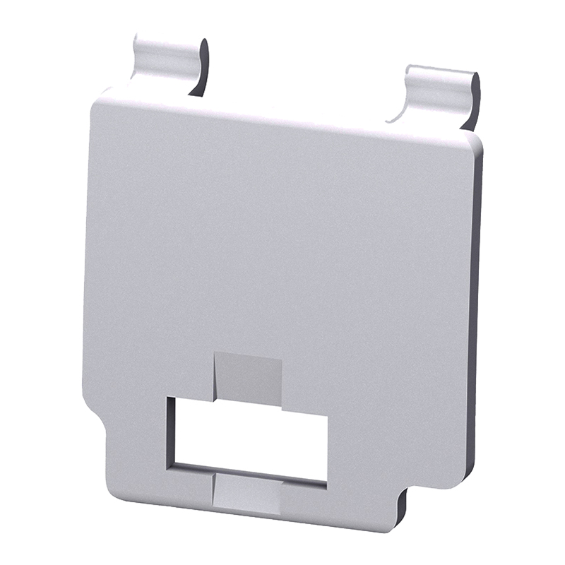
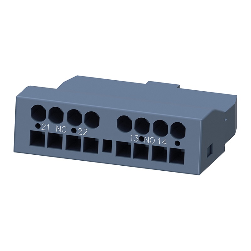
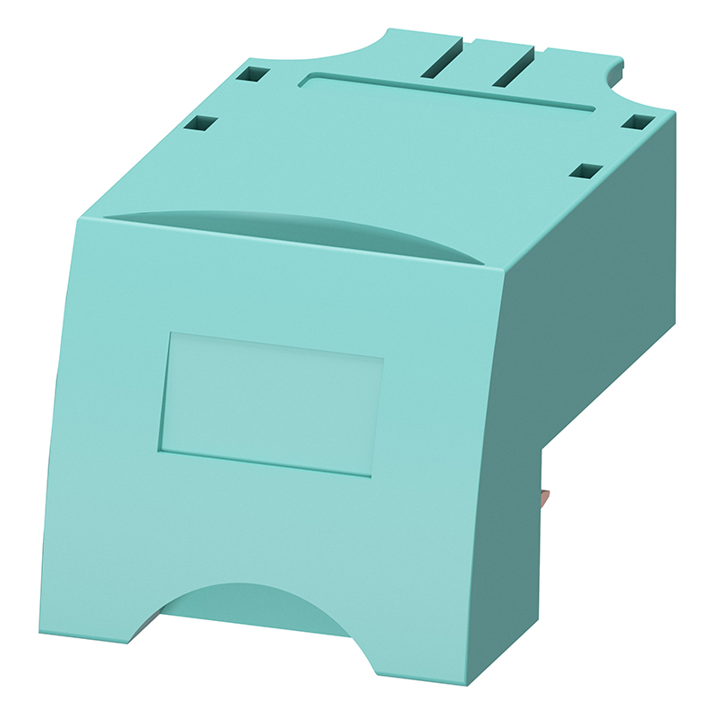
Siemens 3RV2917-7AA00
Brand:
Series:
3RV2
Scope of Application:
3RV2
Auxiliary Contacts:
-
Product Type:
Contactor base
Installation:
Bottom installation
Model:
3RV2917-7AA00
Order Number:
3RV29177AA00
Description:
Siemens 3RV2917-7AA00, contactor base, method bottom installation, applicable range 3RV2
Product parameters
| Product attributes | Attribute value | Filter product attributes |
|---|---|---|
| Brand: | Siemens | |
| Series: | 3RV2 | |
| Scope of Application: | 3RV2 | |
| Auxiliary Contacts: | - | |
| Product Type: | Contactor base | |
| Installation: | Bottom installation |
Products with the same attribute : 0
Show details
Series Overview
Series Overview
- The 3RV2 circuit breaker is a compact - type current - limiting motor starting protection circuit breaker. It can be used for the switching on/off and protection of three - phase induction motors (with a maximum power of up to 55kW at AC 400V) and other loads (with a maximum rated current of up to 100A).
Specification Notes
- The 3RV2 circuit breaker includes 4 types of specifications:
- S00 specification — 45mm wide, maximum rated current 16A, applicable induction motor maximum 7.5kW at AC 400V.
- S0 specification — 45mm wide, maximum rated current 40A, applicable induction motor maximum 18.5kW at AC 400V.
- S2 specification — 55mm wide, maximum rated current 80A, applicable induction motor maximum 37kW at AC 400V.
- S3 specification — 70mm wide, maximum rated current 100A, applicable induction motor maximum 55kW at AC 400V.
Operating Conditions
- The 3RV2 circuit breaker is suitable for any climate and is applied in normal operating environments of enclosed spaces (such as dust - free, free of corrosive gases or harmful gases). When installed in dusty and humid places, a suitable protective cover needs to be equipped.
- The 3RV2 circuit breaker can have wires connected from the top or the bottom.
- For the ambient temperature allowed by the circuit breaker, the maximum breaking capacity, the tripping action current, and other conditions, refer to the specific technical data and tripping characteristic curves in this manual.
- The 3RV2 circuit breaker can be used in IT systems (IT networks), but the different short - circuit breaking capacities in IT systems should be considered.
- Even for motors with the same rated power, due to the instantaneous peak current, their operating current, starting current, and current peak value are all different. Therefore, the rated value of the motor in the selection table can only represent guide data. The actual rated data and starting data of the motor are very important for selecting a suitable circuit breaker. This principle also applies to circuit breakers for transformer protection.
Design
- Wiring Terminals
- The 3RV2 circuit breaker can provide screw - type, spring - type, or ring - type wiring terminals. Appropriate wiring types can be flexibly selected according to different application requirements.
- Installation
- The 3RV2 circuit breaker can be clipped on a 35mm standard rail.
- S00 and S0 specifications can optionally use 3RV29 28 - 0B socket strips for direct screw - fixing on the base plate.
Functions
- Trips
- The 3RV2 motor protection circuit breaker is equipped with a reverse - action dual - metal thermal overload trip and an instantaneous current trip (electromagnetic short - circuit trip).
- The thermal overload trip current can be adjusted according to the load current. To avoid faults during motor starting, the short - circuit trip current is set at 13 times the rated current of the circuit breaker as a fixed value.
- To prevent tripping caused by inrush current of a distorted transformer, the circuit breaker for power - side transformer protection has the short - circuit trip current set at 20 times the rated current of the transformer.
- Trip Classes
- The trip class of the thermal overload trip is based on the trip time (tA) at 7.2 times the cold - state operating current (from IEC 60947 - 4 standard):
- CLASS10A : 2s < tA ≤ 10s
- CLASS10 : 4s < tA ≤ 10s
- CLASS20 : 6s < tA ≤ 20s
- CLASS30 : 9s < tA ≤ 30s
- The motor protection circuit breaker must trip within this time range.
- The trip class of the thermal overload trip is based on the trip time (tA) at 7.2 times the cold - state operating current (from IEC 60947 - 4 standard):
- Operating Mechanism
- The 3RV2 circuit breaker operates through a rotary operating mechanism. When the circuit breaker trips, the rotary operating mechanism will switch to the “Tripped” position for indication. Before the circuit breaker is reclosed, the rotary operating mechanism must be manually reset to the “0” position to prevent the circuit breaker from being closed before the fault is eliminated. After that, the circuit breaker can be placed in the “I” position.
- All rotary operating mechanisms can be locked in the “0” position with a padlock (padlock shackle diameter 3.5mm - 4.5mm).
- The isolation function of the 3RV2 circuit breaker complies with the standard IEC 60947 - 2.
Configuration
- Preventing Accidental Tripping
- Since the motor protection circuit breaker has phase - failure protection function, current must pass through all three phases during connection.
- Short - Circuit Protection
- When a short - circuit occurs, the short - circuit trip of the 3RV2 circuit breaker can isolate the faulty load - fed circuit from the power supply, thus preventing further losses.
- Most models of the 3RV2 circuit breaker have a rated ultimate short - circuit breaking capacity of over 55kA at AC 400V, and the short - circuit protection reliability is very high because such high short - circuit currents are usually not encountered.
- Motor Protection
- The tripping characteristic of the 3RV20 motor protection circuit breaker is mainly designed to protect three - phase induction motors.
- The rated current In of the protected motor can be adjusted with the setting knob. The short - circuit trip current is fixedly set at 13 times the rated current of the motor protection circuit breaker. In this way, the motor will not trip due to faults during starting and can be properly protected.
- If phase failure and over - current occur due to phase faults, the phase - failure protection of the motor protection circuit breaker will trip in time. The design trip class of the motor protection circuit breaker equipped with a thermal overload trip is CLASS10 (3RV203/204 can optionally have Class20 specification).
- System Protection
- The 3RV20 motor protection circuit breaker used for motor protection can also be used for system protection.
- To prevent early tripping due to phase - failure protection, the protected object must be a three - phase symmetric load. If it is a single - phase load, the circuits must be connected in series.
- Short - Circuit Protection of Starter Combinations
- The 3RV23 circuit breaker can be combined with contactors and overload relays for short - circuit protection of starter combinations.
- Similar to the motor protection circuit breaker for protecting motors, the 3RV23 circuit breaker is also equipped with a short - circuit trip, and its trip value is set at 13 times the rated current of the circuit breaker as a fixed value, without an overload trip.
- Once an overload occurs, the overload relay will trigger the contactor to open, while the circuit breaker remains closed. Only when a short - circuit occurs in the feeder line will the circuit breaker trip.
- Since the circuit breaker used for starter combinations cannot protect the motor independently and cannot prevent overload by itself, it must be used with an overload relay.
- Transformer Protection
- When controlling a transformer on the power supply side, the instantaneous current generated when connecting the transformer often causes false tripping of the protection mechanism. Therefore, the short - circuit trip value of the 3RV24 circuit breaker used for transformer protection is set at 20 times the rated current value as a fixed value, so it can be used for transformers where the inrush current on the power supply side is 30 times the rated current.
- Transformers with low inrush current control do not need to use such circuit breakers and can use the 3RV20 motor protection circuit breaker for motor protection.
- Main Switch and Emergency Stop Switch
- The 3RV2 circuit breaker has an isolation function complying with IEC 60947 - 2 and can be used as a main switch and an emergency stop switch.
Application Categories
- The 3RV2 circuit breaker can be used for:
- Motor protection
- System protection
- Short - circuit protection of starter combinations
- Transformer protection
- As main switches and emergency stop switches
- IT systems (IT networks)
- DC circuits
- Explosion - proof applications (ATEX)
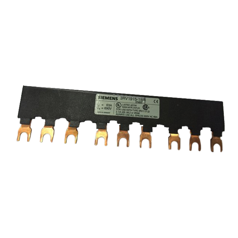
Insulated Three - Phase Busbar System
- The wiring of the 3RV2 circuit breaker in the three - phase busbar system is more convenient, time - saving, and clear, and is suitable for circuit breakers below 32A of S00/S0 specifications.
- The busbar can be applied to 2 to 5 circuit breakers. When expansion is needed, the second busbar can be rotated 180° and inserted into the terminal of the last circuit breaker in parallel with the first one.
- The circuit breakers of S00 and S0 specifications can be combined using the same busbar.
- The three - phase busbar system has a finger protection function and is suitable for any short - circuit situation that may occur on the outgoing line side of the circuit breaker.
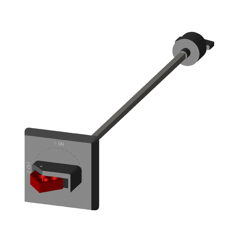
Door - Coupled Rotary Operating Mechanism
- The circuit breaker can be installed inside the cabinet and operated outside the cabinet through the door - coupled rotary operating mechanism. When the cabinet door with the circuit breaker installed is closed, the operating mechanism is in a locked state. When the circuit breaker is in the closed position, the door interlock device can be used to prevent the cabinet door from being opened accidentally. Only maintenance personnel can open the locking mechanism. When the switch is in the open position, the rotary operating mechanism can be locked with up to three padlocks, which can also prevent the cabinet door from being opened due to negligence.

Rachel
Industrial Control Sales Specialist: Focuses on delivering high-performance, cost-effective industrial control products. Offers end-to-end one-stop procurement support—covering rapid quotation, streamlined order fulfillment, and responsive after-sales service—to simplify clients’ procurement processes.
Email: Anthony@icxsg.com
We offer competitive product pricing. For fast support, send your email, phone, address, and the product model & quantity you want—we’ll reach out quickly!
We typically respond via email within one business day! You can also contact us at Anthony@icxsg.com