






 English
 Français
 Deutsch
 Português
 Español
 русский
  한국어
한국어 العربية
 Italiano
 Indonesia
 Schweiz
 Polski
 Nederlands
 ישראל - עברית
 Perzisch
 ไทย
ไทย 日本語
日本語 ኢትዮ-አማርኛ
 Việt Nam
 Kiswahili
 Srpski
 Ελληνικά
 简体中文
简体中文
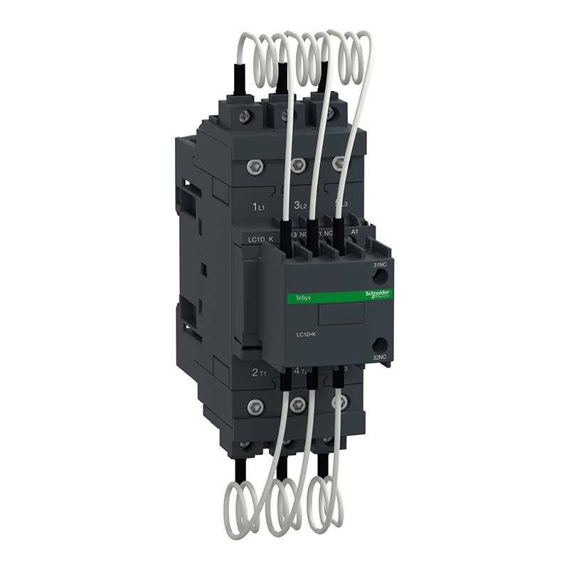
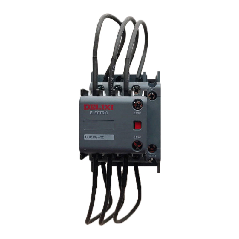
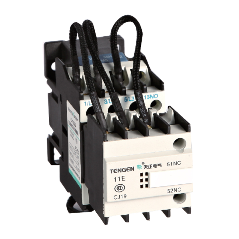
TENGEN TGCC1-9512 220V 50HZ
Brand:
Series:
TGCC1
Switching Capacitor Capacity:
35kvar
Control Coil Voltage:
220VAC
Auxiliary Contacts:
1NO+2NC
Rated Current:
73A
Model:
TGCC1-9512 220V 50HZ (Xiangyun 3.0)
Order Number:
339011800256
Description:
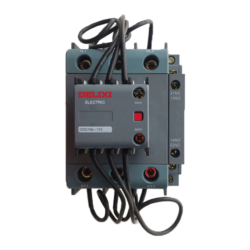
TENGEN capacitor contactor TGCC1-9512 220V 50HZ, auxiliary contact 1NO+2NC, switching capacitor capacity 35kvar, rated current 73A
Product parameters
| Product attributes | Attribute value | Filter product attributes |
|---|---|---|
| Brand: | TENGEN | |
| Series: | TGCC1 | |
| Switching Capacitor Capacity: | 35kvar | |
| Control Coil Voltage: | 220VAC | |
| Auxiliary Contacts: | 1NO+2NC | |
| Rated Current: | 73A |
Products with the same attribute : 0
Show details
Series Overview
Series Overview
Product Overview
- The TGCC1 series contactors for switching capacitors (hereinafter referred to as contactors) are mainly used in power systems with an AC frequency of 50Hz (or 60Hz), a rated operating voltage of up to 690V. When used in the AC - 6b category, they can control capacitor banks with a capacity of up to 60kvar to connect and disconnect shunt capacitors for the purpose of improving the power factor.
- This product complies with GB/T 14048.4 and IEC60947 - 4 - 1.
Normal Operating Conditions and Installation Conditions
- Ambient Temperature: The extreme operating temperature ranges from - 35°C to + 70°C; the normal operating temperature ranges from - 5°C to + 40°C, and the average value within 24 hours does not exceed + 35°C.
- Installation Conditions: The inclination of the installation surface from the vertical plane shall not be greater than ± 22.5°, and the installation category is Class III.
- Pollution Degree: Level 3.
- Altitude: Not exceeding 2000m.
- Atmospheric Conditions: When the maximum temperature is + 70°C, the relative humidity of the air shall not exceed 50%. At lower temperatures, a relatively high relative humidity is allowed, for example, 90% at 20°C. Special measures shall be taken for condensation occasionally generated due to temperature changes.
- The product shall be installed and used in a place without obvious shaking, impact, and vibration.
Structural Features
- The contactor is of a straight - moving double - break type, and the contact system is arranged in two layers: upper and lower. The upper layer is equipped with three current - limiting resistors, that is, the inrush current suppression device. When closing, the current - limiting contacts close first, and after a short delay, the working contacts close. The permanent magnet in the current - limiting contacts is released under the action of the spring, disconnecting the current - limiting resistors, so that the capacitors work normally.
- The contactor has the characteristics of small volume, light weight, low power consumption, long service life, safety, and reliability.
- Except for being installed with screws, the TGCC1 - 25 ~ 43 can be installed on a 35mm standard guide rail.
- The TGCC1 - 63 ~ 95 can be installed on a 35mm or 75mm standard guide rail.
Installation, Use, and Maintenance
- Before installation, check whether the technical data (such as rated voltage, rated current, etc.) on the coil match the power supply. And note that the two wiring marks A2 at different ends are the same contact point; when wiring, just select A1 and any one of A2.
- During installation, the specified installation conditions shall be followed. The wiring terminal A1 of the coil shall be facing upward, which conforms to people's visual habits. For the TGCC1 - 63 ~ 95 products, if multi - strand wires are used for wiring, terminal lugs shall be used.
- When wiring, pay attention to the wiring terminal marks: 1/L1, 3/L2, 5/L3 are the main circuit incoming terminals; 2/T1, 4/T2, 6/T3 are the main circuit outgoing terminals; 21, 22 and 31, 32 are the normally closed auxiliary wiring terminals; 13, 14 and 33, 34 are the normally open auxiliary wiring terminals.
- After installation, if the wires between phases are piled up together, they must be separated and neatly arranged, and at the same time, prevent the wiring terminals from breaking.
- Tighten the wiring screws. After checking that the wiring is correct, and when the main contacts are not live, apply the rated control power supply voltage to the coil for the number of times specified in the table, and put it into use after confirming that the test action is correct.
- When the capacitor is closed, if the inrush current is too large and exceeds the suppression capacity of this contactor, the resistor may be burned out. At this time, the resistor can be replaced and then continue to be used.
- For the electrical equipment selected for the electrical measuring device in the reactive power compensation equipment, its insulation voltage shall be greater than 2Ue to avoid damaging the contactor due to the failure of the electrical measuring device.
- When using, please note that this contactor cannot be used for spot welding, otherwise the resistor will be burned out.
- Regularly tighten the contactor's wiring terminals and remove accumulated dust.
- Do not let foreign objects fall into the product.
Series Overview
Series Overview
Product Overview
- The TGCC1 series contactors for switching capacitors (hereinafter referred to as contactors) are mainly used in power systems with an AC frequency of 50Hz (or 60Hz), a rated operating voltage of up to 690V. When used in the AC - 6b category, they can control capacitor banks with a capacity of up to 60kvar to connect and disconnect shunt capacitors for the purpose of improving the power factor.
- This product complies with GB/T 14048.4 and IEC60947 - 4 - 1.
Normal Operating Conditions and Installation Conditions
- Ambient Temperature: The extreme operating temperature ranges from - 35°C to + 70°C; the normal operating temperature ranges from - 5°C to + 40°C, and the average value within 24 hours does not exceed + 35°C.
- Installation Conditions: The inclination of the installation surface from the vertical plane shall not be greater than ± 22.5°, and the installation category is Class III.
- Pollution Degree: Level 3.
- Altitude: Not exceeding 2000m.
- Atmospheric Conditions: When the maximum temperature is + 70°C, the relative humidity of the air shall not exceed 50%. At lower temperatures, a relatively high relative humidity is allowed, for example, 90% at 20°C. Special measures shall be taken for condensation occasionally generated due to temperature changes.
- The product shall be installed and used in a place without obvious shaking, impact, and vibration.
Structural Features
- The contactor is of a straight - moving double - break type, and the contact system is arranged in two layers: upper and lower. The upper layer is equipped with three current - limiting resistors, that is, the inrush current suppression device. When closing, the current - limiting contacts close first, and after a short delay, the working contacts close. The permanent magnet in the current - limiting contacts is released under the action of the spring, disconnecting the current - limiting resistors, so that the capacitors work normally.
- The contactor has the characteristics of small volume, light weight, low power consumption, long service life, safety, and reliability.
- Except for being installed with screws, the TGCC1 - 25 ~ 43 can be installed on a 35mm standard guide rail.
- The TGCC1 - 63 ~ 95 can be installed on a 35mm or 75mm standard guide rail.
Installation, Use, and Maintenance
- Before installation, check whether the technical data (such as rated voltage, rated current, etc.) on the coil match the power supply. And note that the two wiring marks A2 at different ends are the same contact point; when wiring, just select A1 and any one of A2.
- During installation, the specified installation conditions shall be followed. The wiring terminal A1 of the coil shall be facing upward, which conforms to people's visual habits. For the TGCC1 - 63 ~ 95 products, if multi - strand wires are used for wiring, terminal lugs shall be used.
- When wiring, pay attention to the wiring terminal marks: 1/L1, 3/L2, 5/L3 are the main circuit incoming terminals; 2/T1, 4/T2, 6/T3 are the main circuit outgoing terminals; 21, 22 and 31, 32 are the normally closed auxiliary wiring terminals; 13, 14 and 33, 34 are the normally open auxiliary wiring terminals.
- After installation, if the wires between phases are piled up together, they must be separated and neatly arranged, and at the same time, prevent the wiring terminals from breaking.
- Tighten the wiring screws. After checking that the wiring is correct, and when the main contacts are not live, apply the rated control power supply voltage to the coil for the number of times specified in the table, and put it into use after confirming that the test action is correct.
- When the capacitor is closed, if the inrush current is too large and exceeds the suppression capacity of this contactor, the resistor may be burned out. At this time, the resistor can be replaced and then continue to be used.
- For the electrical equipment selected for the electrical measuring device in the reactive power compensation equipment, its insulation voltage shall be greater than 2Ue to avoid damaging the contactor due to the failure of the electrical measuring device.
- When using, please note that this contactor cannot be used for spot welding, otherwise the resistor will be burned out.
- Regularly tighten the contactor's wiring terminals and remove accumulated dust.
- Do not let foreign objects fall into the product.

Rachel
Industrial Control Sales Specialist: Focuses on delivering high-performance, cost-effective industrial control products. Offers end-to-end one-stop procurement support—covering rapid quotation, streamlined order fulfillment, and responsive after-sales service—to simplify clients’ procurement processes.
Email: Anthony@icxsg.com
We offer competitive product pricing. For fast support, send your email, phone, address, and the product model & quantity you want—we’ll reach out quickly!
We typically respond via email within one business day! You can also contact us at Anthony@icxsg.com