Internal Accessories
Auxiliary Contacts
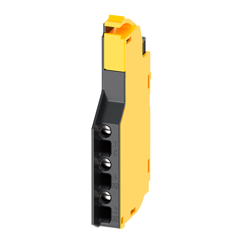
● All auxiliary and alarm contacts for 3VM molded case circuit breakers belong to the range of integrated accessories. The auxiliary contacts are simply snapped into place and connected to the left and right sides of the handle via the accessory compartment provided on the front of the unit.
● The function of the auxiliary contact MX is to indicate the position of the main contacts of the molded case circuit breaker. The auxiliary contact opens and closes synchronously with the main contacts of the molded case circuit breaker.
● The trip alarm contact TAS signals whenever the circuit breaker trips, regardless of the cause of tripping. The trip alarm contact operates whenever the molded case circuit breaker switches to the TRIP position.
● Dedicated EMC-compatible components are available for applications requiring connection of auxiliary contact signals to automation systems.
Auxiliary Releases
● Auxiliary releases enable remote electrical tripping of the circuit breaker. They can be used to monitor control circuits or main circuits, providing protection against situations such as unexpected restart after a power failure.
● The undervoltage release trips the 3VM molded case circuit breaker when the rated voltage of the monitored circuit drops below the minimum permissible limit or fails completely.
● The
shunt trip release can be used to trip the 3VM molded case circuit breaker remotely.
Advantages
● Internal accessories are very easy to install. They can be snapped into place in the accessory compartment and connected to the left and right sides of the handle without tools.
● Accessories are connected via screw-type terminals suitable for auxiliary conductors with a maximum cross-section of 2.5 mm². These terminals are located on the front of the unit for convenient wiring.
● All auxiliary and alarm contacts are designed as changeover contacts, offering high design and installation flexibility.
● Symbols engraved on the accessory compartment cover indicate the installation positions of the internal accessories.
Manual Operating Mechanisms
Overview
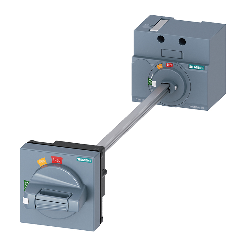
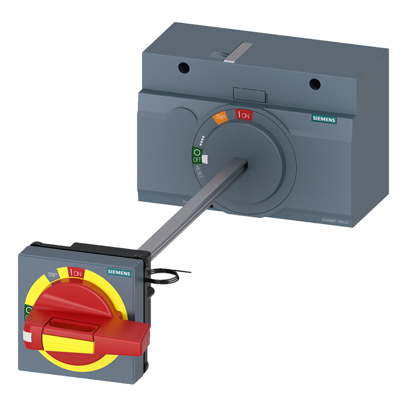
● Manual operating mechanisms are used for the manual operation of 3VM molded case circuit breakers, either directly on the breaker or through the cabinet door.
Front Rotary Operating Mechanism
● The front rotary operating mechanism is mounted directly on the molded case circuit breaker, with or without a door interlock system. This operating mechanism has a degree of protection of IP30. The door interlock mechanism locks the cabinet door after the molded case circuit breaker is switched ON, but can also be unlocked if necessary.
Door-Coupled Rotary Operating Mechanism
● The door-coupled rotary operating mechanism allows operation of the molded case circuit breaker from the cabinet door. The external operating handle has a degree of protection of IP65 and features a door interlock system with tolerance compensation.
Connection Technology
Overview
● The proper functioning of electrical installations, especially safety installations, depends not only on the design and quality of the components but also on the installation method. The following aspects of the electrical installation are crucial for the safe and correct connection of 3VM molded case circuit breakers: Installation method, such as connection to cables or busbars; Selection of cables and busbars; Installation medium, such as rigid or flexible media.
● The following product catalog pages provide all the information required to ensure the safe connection of 3VM molded case circuit breakers.
● The connection technology for 3VM molded case circuit breakers enables simple, efficient commissioning and meets all installation requirements.
● To achieve this, Siemens offers a comprehensive product line of connection components.
Front Terminals
● The product line of connection components for molded case circuit breakers includes a wide range of front cable and busbar connection terminals.
● Connection technology available ex-factory or factory-installed.
● All 3VM molded case circuit breakers are equipped as standard with screw terminals on the line and load sides.
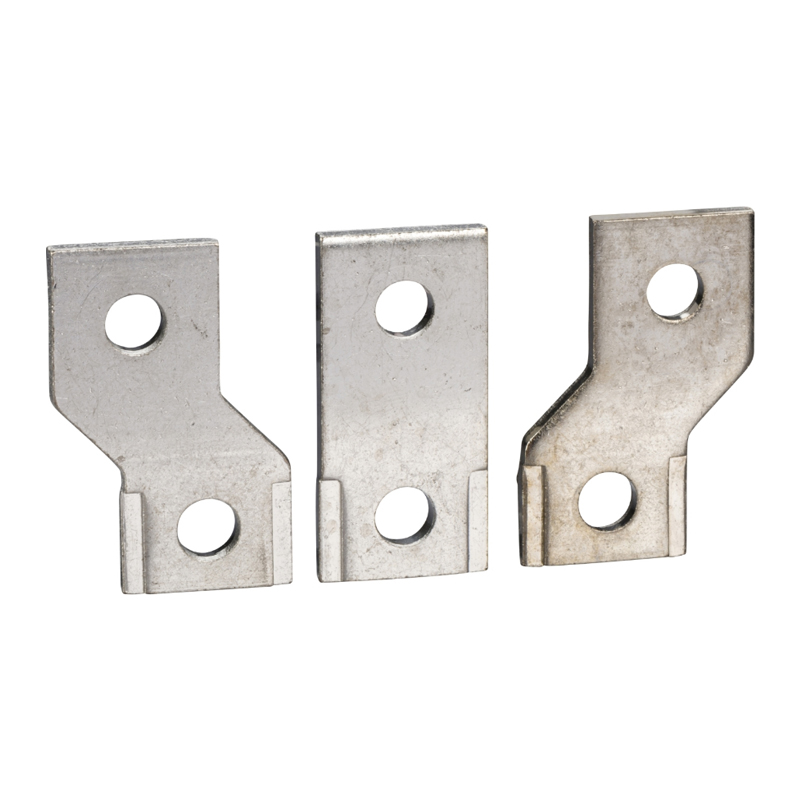
● Insulated copper busbars with cable lugs and cables can be connected directly to the screw terminals. Furthermore, all extension connection busbars are assembled on the molded case circuit breaker via screw terminals: Front extension busbars (phase barriers included in scope of supply); Front widened busbars (phase barriers included in scope of supply).
● Insulation measures (phase barriers or terminal covers) are recommended. Insulation is mandatory for certain auxiliary components (these accessories are included in the scope of supply of the relevant components).
Other Connection Accessories
● Connection accessories include a wide range of insulation components and secondary wiring connection accessories, which must be ordered separately.
● Insulation accessories: Phase barriers, terminal covers, etc.
● Auxiliary conductor terminal accessories: Terminal blocks, busbar secondary connections, etc.
Terminal Covers
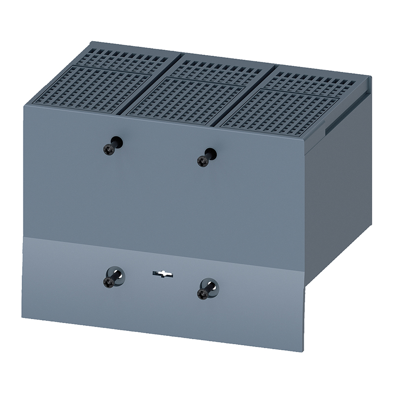
● Terminal covers are insulation accessories and sealed insulation accessories that prevent accidental contact with the main current path. When installed on the circuit breaker, the front terminal cover provides a degree of protection of IP4x; when correctly installed on the line and load sides of the circuit breaker, it provides IP2x. All terminal covers have a groove on the inner surface that can be drilled through if necessary.
● Short terminal covers can generally be installed on all types of front terminals without exceeding the geometric dimensions (termination area) of the molded case circuit breaker (e.g., terminal blocks, screw terminals, etc.).
● Extended terminal covers are required when installing extension busbars or external terminals (terminals that extend beyond the termination area dimensions of the molded case circuit breaker). The extended terminal cover consists of two parts: an insulating plate and the upper part of the terminal cover. The two parts are connected via screws to achieve the specified protection level.
● Wide terminal covers are required when installing widened connection busbars. This extended terminal cover consists of two parts: a widened insulating plate and the upper part of the terminal cover. The two parts are connected via screws to achieve the specified protection level.
Insulating Plates
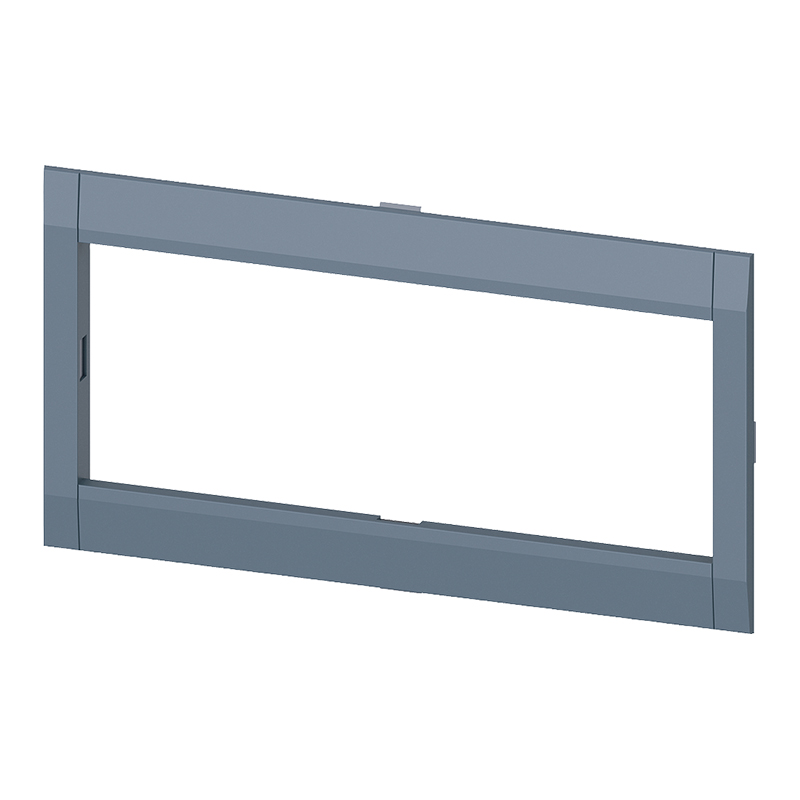
● Insulating plates serve to insulate the main terminals of the molded case circuit breaker from the mounting plate (cabinet).
● Insulating plate: For example, used in combination with extension busbars.
● Widened insulating plate: For example, used in combination with widened connection busbars.
Auxiliary Conductor Terminals
● Ordered round conductor terminals can be supplied with or without auxiliary conductor terminals. The following accessories allow auxiliary conductor terminals to be used in combination with terminal blocks or busbar connectors:
● Auxiliary conductor terminal for terminal blocks: This terminal is fixed via the screw in the terminal block of the cable.
● Auxiliary conductor terminal for busbars: This terminal is fixed directly to the busbar via a screw.
● All auxiliary conductor terminals are suitable for a load current of up to 6 A. Cables with a maximum cross-section of 2.5 mm² can be connected.
Advantages
● High flexibility.
● Cables and busbars can be connected to the 3VM molded case circuit breaker quickly and conveniently.
Plug-in Technology
Overview
● Using plug-in technology enables the fast and safe installation/removal or replacement of 3VM molded case circuit breakers. Here, the cables or busbars of the main current path are connected to the connectors of the plug-in interface.
● The design of the termination area for these models corresponds to that of the molded case circuit breaker termination area, but differs slightly in dimensions due to different requirements for contact gap and clearance.
● This means the available connection technology can be used for the plug-in interface in the same way.
● Plug-in technology is cost-effective, space-saving, and enables fast circuit breaker replacement. The main current path is connected to the connectors of the plug-in base. The circuit breaker has plug-in contacts at the rear. When the circuit breaker plug is inserted into the base, the plug-in contacts slide into the tulip contacts on the base side and connect the main current path to the circuit breaker.
● Additionally, auxiliary circuit connectors are available to connect auxiliary and control signals from the molded case circuit breaker externally. Plug-in units are available as complete kits or as conversion kits for circuit breakers (including terminal covers secured with screws).
Residual Current Devices
Overview
● Residual Current Devices (RCDs) can be used to prevent or reduce dangerous residual currents that pose a risk to the safety of persons and livestock or can cause property damage. These devices are available as accessories for the 3VM series circuit breakers, applicable up to the highest-rated breakers. Residual current devices detect pure sinusoidal AC residual currents and pulsating DC residual currents (Type A). The combination of a molded case circuit breaker or disconnector with a residual current device complies with the requirements of IEC 60947-2 Appendix B.
● These residual current devices feature:
● Compact design.
● 45 mm cover size.
● LED indicators for ready status and pre-alarm.
● Trip signal provided on the device and via electrical contacts.
● Manual acknowledgment via the reset button on the residual current device after tripping.
● The BCD110 and BCD210 devices feature a compact L-shaped design with a cover size of 45 mm for operation and display components. They are suitable for DIN rail mounting. The depth of the combination device (circuit breaker and residual current device) is 70 mm, making it ideally suited for installation in distribution cabinets.
● These residual current devices are mounted on the left side of the circuit breaker. Thanks to feed-through technology, cables can be connected directly to the terminal blocks. Wiring the residual current device/circuit breaker combination requires minimal time. In the event of a residual current, the circuit breaker trips via the HCH (Residual Current Release) located in the left accessory compartment of the circuit breaker; this release is included in the scope of supply. However, this HCH can also be used independently of the residual current device as a shunt trip release via a floating contact.
● On the "2" series residual current devices (BCD210), tripping can be delayed for up to 3 seconds. This allows, in the event of a fault, only the faulty branch to be disconnected through appropriate selective grading of series-connected residual current devices. Both types are also available as 4-pole versions.
● This residual current device can also be used for applications requiring earth leakage alarm only without tripping. During installation, simply omit installing the HCH.
● In this case, when the residual current device detects a leakage current reaching the set limit, it provides an earth leakage fault signal via the secondary circuit signal output terminals, facilitating the collection and use of this information by other relevant systems.
Locking Technology
Overview
● Using padlocks, the 3VM molded case circuit breaker can be locked in the OFF or ON operating position. Once the molded case circuit breaker is locked in position, it cannot be operated.
Padlock Parts for the Handle
● Using padlock parts mounted on the handle, the 3VM molded case circuit breaker can be locked in the OFF or ON operating position.
● In this position, up to 3 padlocks with shackle diameters between 4.5 mm and 8.5 mm can be installed to prevent handle movement.








 English
 Français
 Deutsch
 Português
 Español
 русский
  한국어
한국어 العربية
 Italiano
 Indonesia
 Schweiz
 Polski
 Nederlands
 ישראל - עברית
 Perzisch
 ไทย
ไทย 日本語
日本語 ኢትዮ-አማርኛ
 Việt Nam
 Kiswahili
 Srpski
 Ελληνικά
 简体中文
简体中文