






 English
 Français
 Deutsch
 Português
 Español
 русский
  한국어
한국어 العربية
 Italiano
 Indonesia
 Schweiz
 Polski
 Nederlands
 ישראל - עברית
 Perzisch
 ไทย
ไทย 日本語
日本語 ኢትዮ-አማርኛ
 Việt Nam
 Kiswahili
 Srpski
 Ελληνικά
 简体中文
简体中文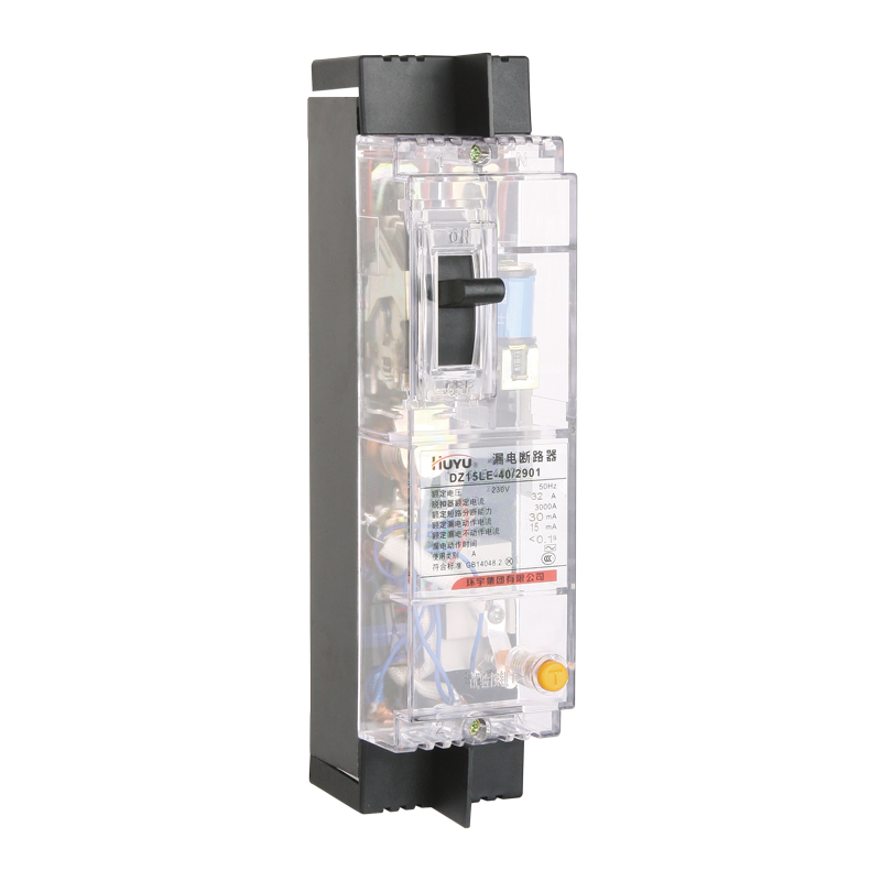
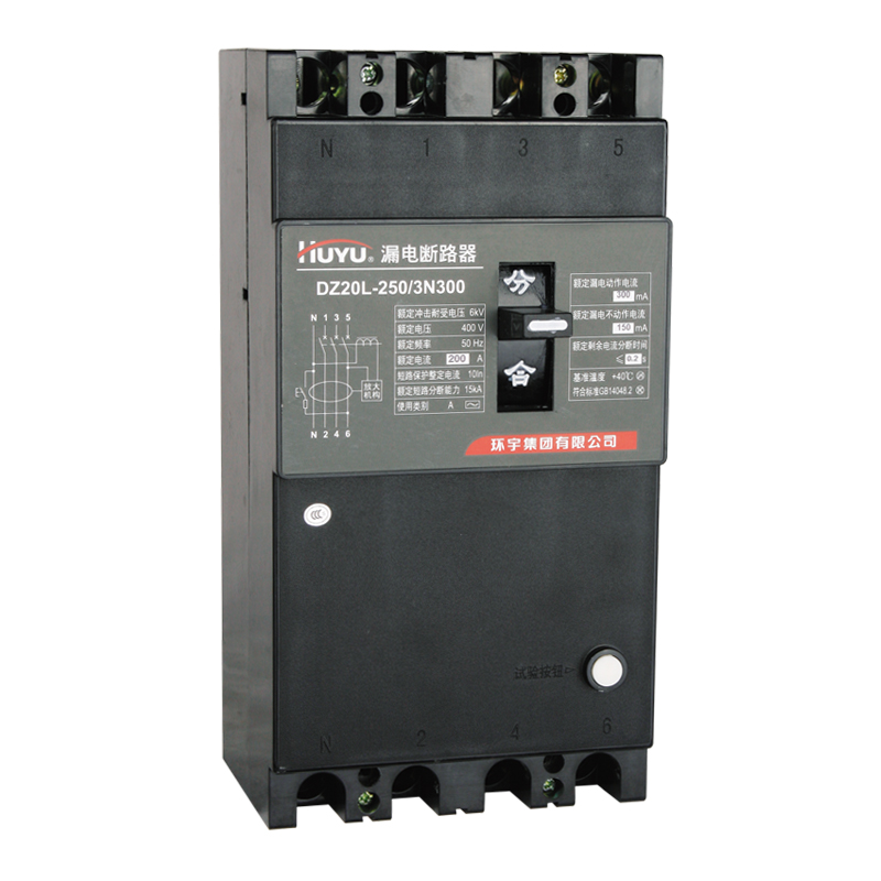
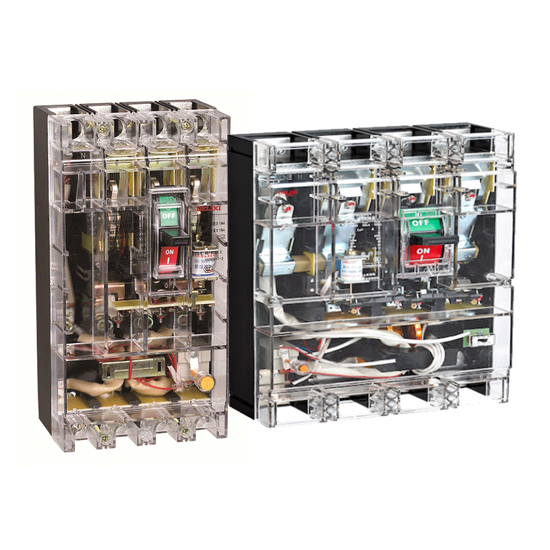
Huyu DZ15L-40/490 40A 100MA with transparent cover plastic case leakage protection circuit breaker
Brand:
Series:
DZ15L
How It Works:
Manual
Frame Current:
40A
Protection Function:
LI
Wiring Method:
Front panel wiring
Poles:
4P
Installation:
Fixed
Breaking Capacity:
3KA
Model:
DZ15L-40/490 40A 100MA with transparent cover
Order Number:
1024100279
Description:
Huyu Molded Case Leakage Protection Circuit Breaker DZ15L-40/490 40A 100MA with transparent cover, fixed, manual, 3KA, front wiring, 4P, frame current 40A
Product parameters
| Product attributes | Attribute value | Filter product attributes |
|---|---|---|
| Brand: | Huyu | |
| Series: | DZ15L | |
| How It Works: | Manual | |
| Frame Current: | 40A | |
| Protection Function: | LI | |
| Wiring Method: | Front panel wiring | |
| Poles: | 4P | |
| Installation: | Fixed | |
| Breaking Capacity: | 3KA |
Products with the same attribute : 0
Show details
Series Overview
Scope of Application
- The DZ15L series Residual Current Circuit Breakers (hereinafter referred to as the circuit breakers) are suitable for circuits with AC 50Hz, rated voltage up to 380V (400V), and rated current up to 100A. They are used for protection against electric shock hazards to persons, and can also be used to prevent fire risks caused by earth fault currents resulting from equipment insulation damage. Additionally, they can protect lines and motors against overload and short circuits, and may also be used for infrequent switching of lines and infrequent starting of motors.
- This product complies with standard GB 14048.2.
Normal Service Conditions
- Altitude: The altitude of the installation site should not exceed 2000m.
- Ambient Air Temperature: Upper limit not exceeding +40°C; average value over 24 hours not exceeding +35°C; lower limit not lower than -5°C.
- Atmospheric Conditions: The relative humidity of the atmosphere should not exceed 50% at the maximum surrounding temperature of +40°C. Higher relative humidity is permissible at lower temperatures. The monthly average maximum relative humidity is 90% when the monthly average temperature is 25°C, taking into account condensation occurring on the product surface due to temperature changes.
- Installation Conditions: Install in locations free from impact, vibration, rain, and snow ingress. The upper terminals are for the power supply side, and the lower terminals are for the load side. The inclination relative to the vertical plane should not exceed 5°.
- Installation Category: III.
- Pollution Degree: 3.
- The external magnetic field at the circuit breaker installation site should not exceed 5 times the Earth's magnetic field in any direction.
Operation and Maintenance
- This series of residual current circuit breakers cannot provide protection against the risk of electric shock resulting from simultaneous contact with both live conductors of the protected circuit.
- The residual current, overload, and short-circuit protection characteristics of the circuit breaker are factory-set. Do not adjust them arbitrarily during use to avoid affecting performance.
- The function of the TEST button is: When the circuit breaker is newly installed or has been in operation for a certain period, press the TEST button while the circuit breaker is closed and energized. If the circuit breaker trips, it indicates normal and reliable operation and it can be put into service. If the circuit breaker fails to trip, it indicates a fault in the circuit breaker or the line, requiring inspection and repair.
- If the circuit breaker trips due to a fault (residual current, overload, or short circuit) in the protected circuit, the operating handle will be in the tripped position (middle position). After identifying the cause and eliminating the fault, first move the operating handle downward to the "OFF" position to reset the mechanism ("re-latch" it) before performing the closing operation.
- After the circuit breaker trips due to a short circuit, inspect the contacts. If the main contacts are severely worn or pitted, maintenance is required.
- Three-pole four-wire residual current circuit breakers must have the neutral conductor connected to enable the electronic circuit to function correctly.
- The load wiring of the residual current circuit breaker must pass through its load terminals. It is not permitted for any phase conductor or the neutral conductor of the load to bypass the residual current circuit breaker, as this will create an artificial "residual current" causing the circuit breaker to fail to close.
- Do not use a 500V DC Megohmmeter to measure insulation resistance or perform dielectric strength tests between the output terminals of a two-pole circuit breaker (terminals 2-4), between the output terminals of a three-pole circuit breaker (terminals 2-6), or between the output terminals of a three-pole four-wire circuit breaker (terminals N-6). If such tests are necessary, the circuit board must be removed first.
- Do not use a 500V DC Megohmmeter to measure insulation resistance or perform dielectric strength tests between the output terminals of a two-pole circuit breaker (terminals 2-4), between the output terminals of a three-pole circuit breaker (terminals 2-6), or between the output terminals of a three-pole four-wire circuit breaker (terminals N-6). If such tests are necessary, the circuit board must be removed first. (Note: This point was duplicated in the source; translated as duplicated for fidelity, but it's the same warning as the point above.)

Rachel
Industrial Control Sales Specialist: Focuses on delivering high-performance, cost-effective industrial control products. Offers end-to-end one-stop procurement support—covering rapid quotation, streamlined order fulfillment, and responsive after-sales service—to simplify clients’ procurement processes.
Email: Anthony@icxsg.com
We offer competitive product pricing. For fast support, send your email, phone, address, and the product model & quantity you want—we’ll reach out quickly!
We typically respond via email within one business day! You can also contact us at Anthony@icxsg.com