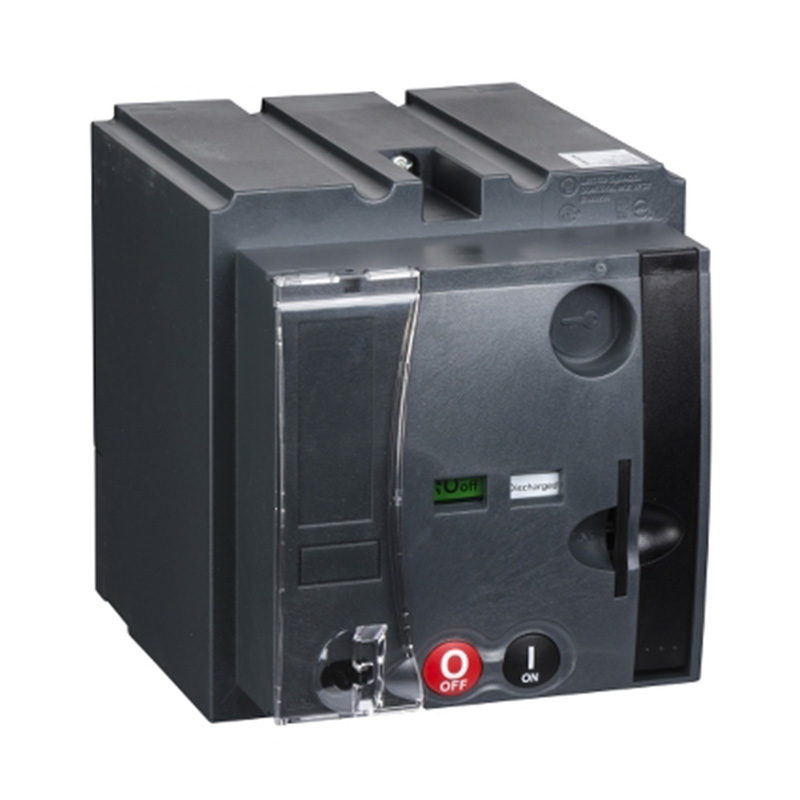
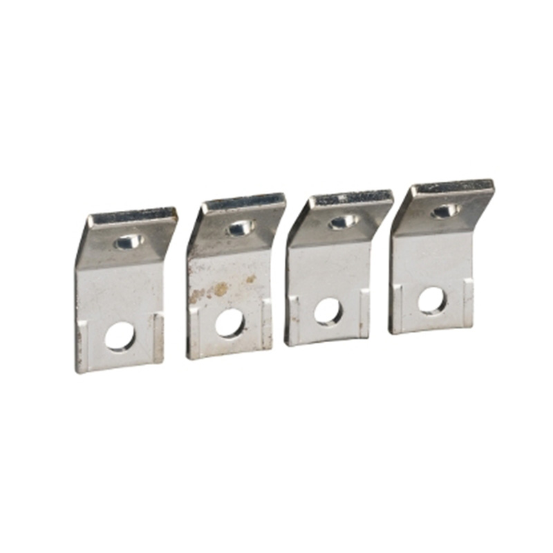
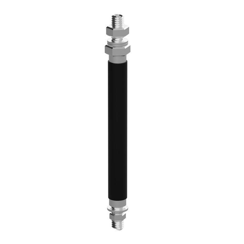
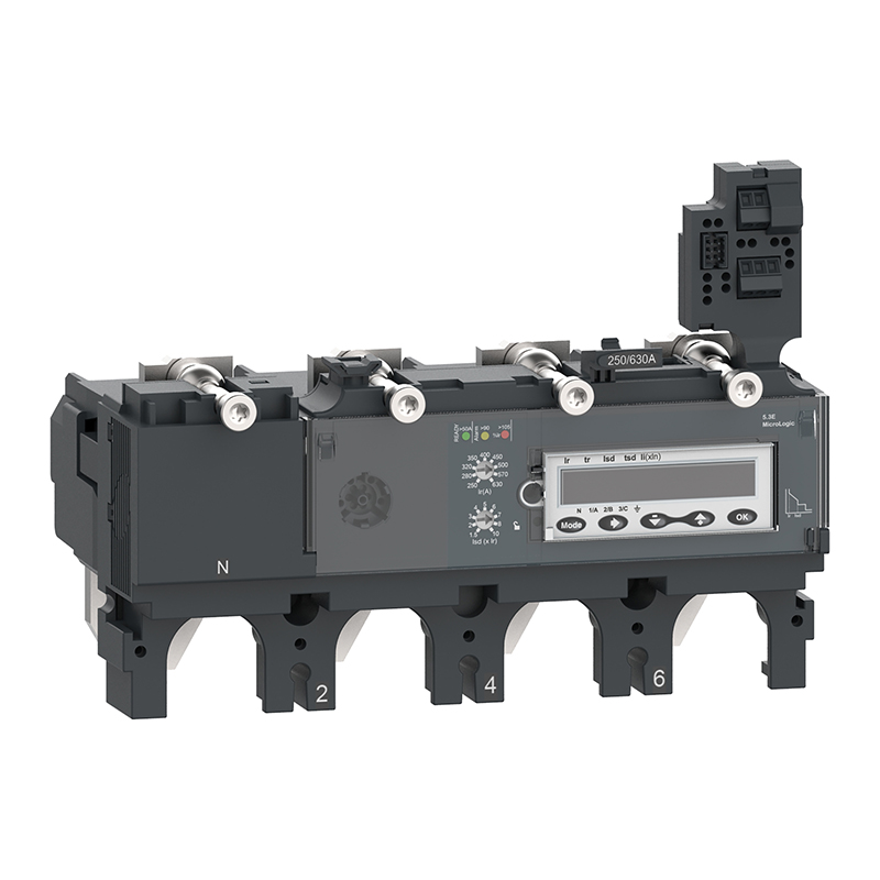
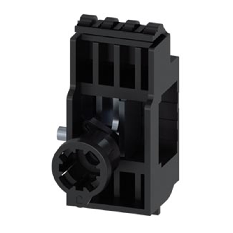
● ComPacT NSX circuit breakers can be installed horizontally or vertically, and either face-up or top-mounted, without affecting their performance. For backplate mounting, the circuit breaker is supplied with two sets of fixing screws (M4), washers, and nuts. These fixing screws can be inserted into the molded mounting holes on the circuit breaker housing and then bolted to the rail or backplate.
Securing the Circuit Breaker Power Connection Wiring
● ComPacT NSX100m/160m offers two standard circuit breakers: one with EverLink™ terminal blocks and one with front-access wiring nuts. The terminal blocks of both standard circuit breakers can be replaced to meet other installation requirements, including EverLink™ terminal blocks with control wiring hole, EverLink™ terminal blocks, lug/busbar connectors, and aluminum connectors.
● Terminal extenders can be used for connecting large cables; they allow connection of cables with lugs or busbars.
Bare Conductors
Standard Terminal Block: EverLink™ Terminal Block
● EverLink™ technology utilizes the creep compensation effect. This technology maintains an accurate and durable tightening torque on the terminal block, ensuring safe and reliable wiring. EverLink™ terminal blocks with control wiring hole are available as spare parts; the control wiring hole can be used for powering electrical accessories, measurement connections, etc., with a maximum current of 10A.
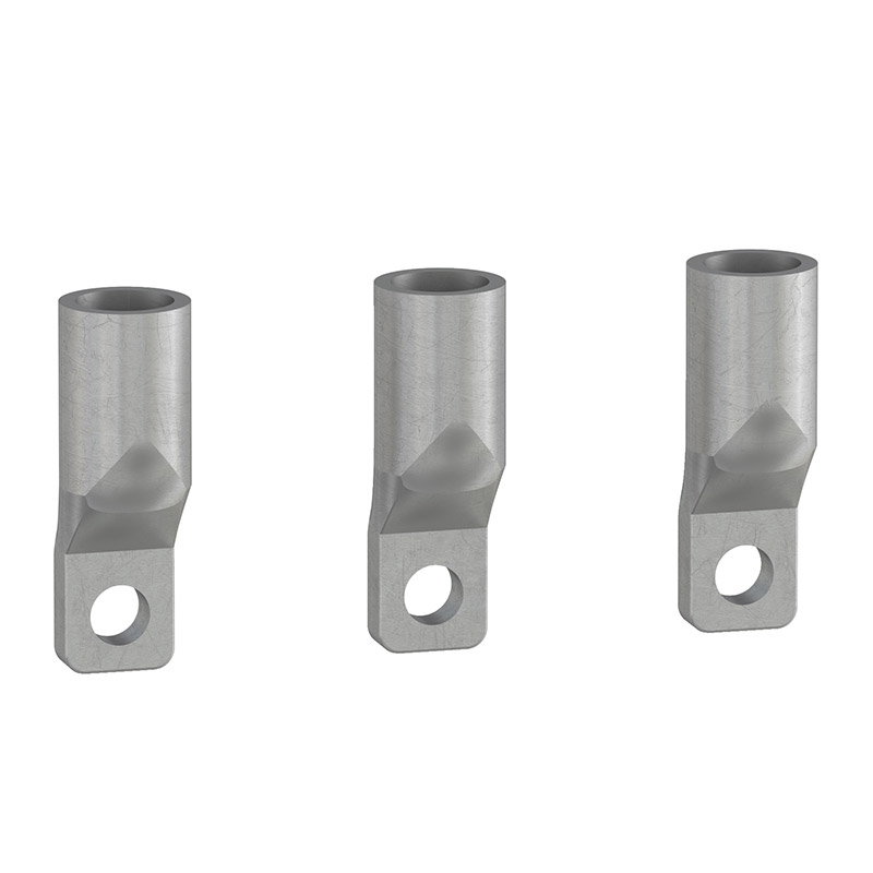
Aluminum Connector, max. 125A
● After removing the EverLink™ terminal block from the standard circuit breaker, an aluminum connector can be installed; the connector snaps onto the circuit breaker terminal. The aluminum connector is made of tin-plated aluminum and can connect both copper and aluminum cables.
Multi-Cable Connector, max. 125A
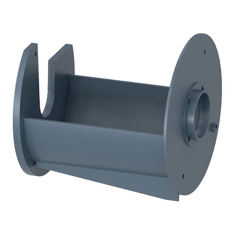
● The multi-cable connector is tightened onto the circuit breaker terminal with a screw. Phase barriers or long terminal shrouds must be used when using multi-cable connectors. The multi-cable connector and phase barriers are supplied together to the customer. Each multi-cable connector can connect 3 or 6 cables.
Busbar or Cable with Lug Lug/Busbar Connection
● ComPacT NSX100m/160m circuit breakers are also available in a standard configuration with front-access wiring nuts (M6) and screws. On-site installation is very convenient, requiring only the replacement of the EverLink block with the screw.
This terminal can be used for:
● Direct connection of insulated busbars or cables with lugs.
● Terminal extenders, providing more wiring options.
● The use of phase barriers or terminal shrouds is recommended. For certain connection accessories, their use is mandatory (in this case, phase barriers are supplied with the connection accessory).
Lugs
● Lugs are available in two models, for aluminum cables and copper cables respectively. Lugs conforming to the connection specifications must be used and must be used in conjunction with phase barriers or long terminal shrouds. When supplied, lugs and phase barriers are provided together to the customer for various wiring applications.
Busbars
● If the switchgear configuration is not tested, insulated busbars must be used for connection.
Terminal Extender
● Terminal extenders are used to increase the pole center distance from 27mm to 35mm. Busbars or cable lugs can be applied to terminal extenders.
● Terminal extenders are supplied standard with M8 screws and phase barriers (incompatible with long terminal shrouds). Depending on the distance between live non-insulated parts and the grounded metal backplate, rear insulating barriers can also be optionally used.
Torque-Limiting Screw
● Torque-limiting screws can be used to tighten
EverLink™, lugs, or busbar connections with the correct torque.
Insulation of Live Parts Long Terminal Shroud IP40
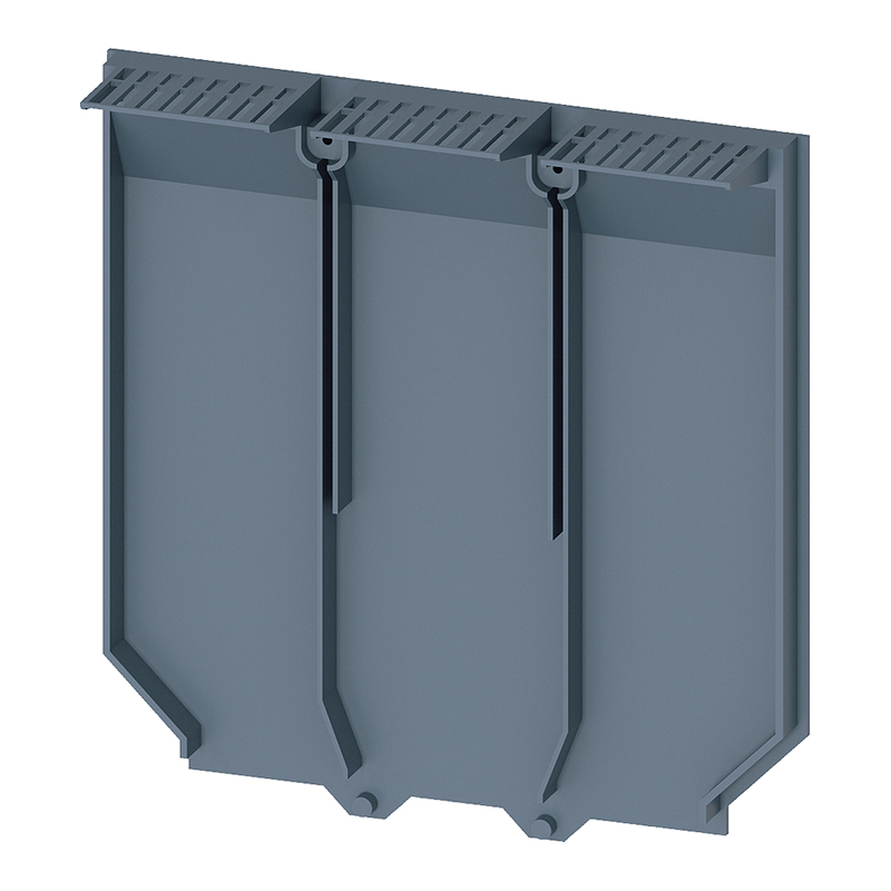
● ComPacT NSX100m/160m 3P or 4P can be configured with long terminal shrouds. Long terminal shrouds can be installed on the line side or load side to prevent direct contact with the power circuit, meeting IP40 protection degree and IK07 mechanical impact protection degree. Furthermore, long terminal shrouds can be used when the product is mounted on a backplate and when electrical accessories are wired. Long terminal shrouds are used for front connection of cables or insulated busbars. The long terminal shroud consists of two parts assembled with screws, achieving IP40 protection degree.
● The upper part has a sliding grid with break-off tabs for precise adaptation to the cable or insulated busbar.
● The rear part completely encloses the wiring area. Locally removable grid sections can be broken off to accommodate connections of various cables with lugs or copper busbars.
Phase Barriers
Phase barriers are safety accessories that ensure insulation at the connection points:
● Easily installed by snapping onto the circuit breaker.
● Incompatible with long terminal shrouds.
● 2 installation methods: short/long insulation.
Rear Insulating Barrier
● The rear insulating barrier is a safety accessory that provides insulation for the rear of the equipment.
Accessory Selection
Standard
All ComPacT NSX circuit breakers and disconnectors have internal reserved positions for installing the following electrical accessories:
2 indication contacts:
● 1 ON/OFF indication contact (OF).
● 1 trip indication contact (SD).
● 1 MN undervoltage release coil or 1 MX shunt trip coil.
Remote Indication
● Circuit breakers with MicroLogic 4.1 trip units can be equipped with an alarm or fault trip indication module SDx to identify the fault type.
● Installation is unaffected when the circuit breaker is fitted with a rotary handle or toggle switch handle.
Accessory Connection
Wiring
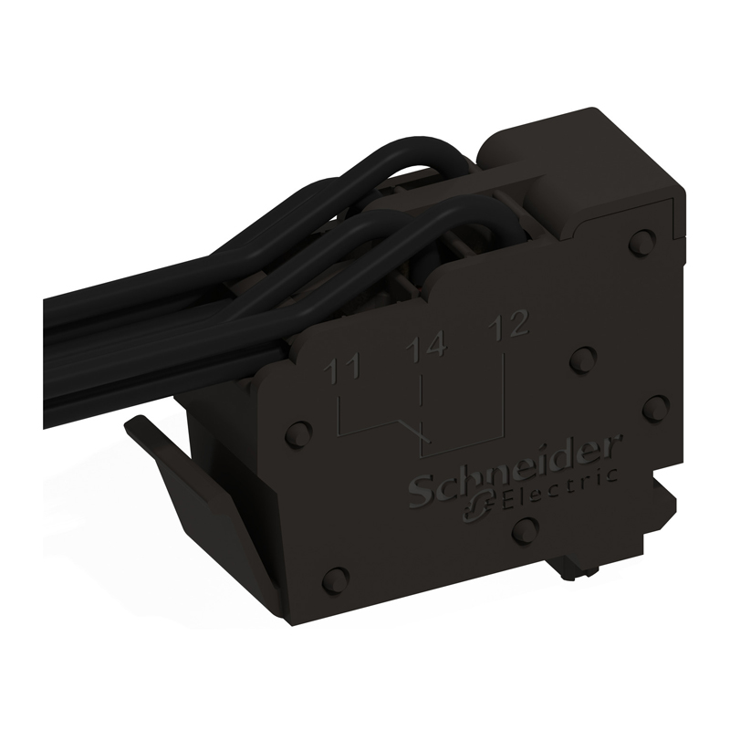
● Electrical accessories have numbered spring-clamp terminals for electrical wiring.
● Maximum wiring capacity for auxiliary switches (OF or SD), MX shunt trip coil, or MN undervoltage release coil is 1.5mm².
● Cables from electrical accessories can exit from any of the four corners of the circuit breaker, or from the protective cover when using a long terminal shroud.
Indication Contacts
Auxiliary and Alarm Indication Contacts
● Universal contacts provide remote indication of circuit breaker status information. Can be used for indication, electrical interlocking, relay control, etc.
● Complies with IEC 60947-5 international standard requirements.
● These contacts are universal changeover type contacts, with normally open (NO) and normally closed (NC) contacts.
ON/OFF - Auxiliary Contact (OF)
● Indicates the position of the circuit breaker contacts.
Trip Indication - Alarm Contact (SD)
Indicates tripping of the circuit breaker due to:
● Electrical fault (overload, short circuit).
● Tripping caused by a shunt trip coil.
● Tripping caused by an undervoltage coil.
● Pressing the trip button.
● The contact resets after the circuit breaker is reset.
Installation and Connection
● Auxiliary contacts (OF) and alarm contacts (SD) snap into slots behind the front cover of the circuit breaker. Installation can be identified by the green marker on the front cover.
● The function provided by the contact depends on its installation position within the circuit breaker.
● Each NO and NC contact's spring-clamp terminal can connect one 0.5...1.5mm² flexible copper wire; the common point can connect two flexible copper wires.
Voltage Release Coils
Shunt Trip Coil (MX) and Undervoltage Release Coil (MN)
● MX and MN release coils cause the circuit breaker to trip via a control signal. They are primarily used for remote emergency opening commands.
● It is recommended to check the system every six months.
Shunt Trip Coil (MX)
● When the control voltage rises above 70% of its rated voltage (Un), the circuit breaker trips.
● Pulse type ≥20ms or maintained signal.
Undervoltage Release Coil (MN)
● When the control voltage drops below 35% of its rated voltage (Un), the circuit breaker trips.
● Tripping is possible but not guaranteed between 35% and 70% of rated voltage.
● Tripping will not occur above 70% of rated voltage.
● The circuit breaker can only close if the voltage exceeds 85% of rated voltage. If undervoltage is present, the circuit breaker cannot be closed, either manually or electrically.
Time-Delay Unit for Undervoltage Release Coil (MN)
● The time-delay unit for the MN release coil avoids nuisance tripping due to transient voltage dips (duration ≤200ms). During short interruptions, a time-delay unit ensures tripping does not occur.
Installation and Connection
● MX and MN release coils snap into slots behind the front cover of the circuit breaker. The type of coil installed can be seen through the transparent window on the front cover.
● Wiring terminals are spring-clamp terminals to ensure fast and reliable connection.
● Each wiring terminal can connect one 0.5...1.5mm² flexible copper wire.
Operation
● After an MX or MN release coil has tripped the circuit breaker, it must be reset before the circuit breaker can be closed.
● The MX or MN trip command has priority over manual closing; if a trip command is always present, the circuit breaker cannot be closed (even temporarily).
● Service life: 50% of the circuit breaker's mechanical life.
Standard
● MX/MN voltage release coils comply with IEC 60947-2 standard.
SDx Module for MicroLogic Vigi 4.1 SDx Module for ELCB
● The SDx module provides alarm and fault indication functions for ComPacT NSX earth leakage circuit breakers (ELCB) equipped with MicroLogic 4.1 (ELCB) trip units. The module has 2 sets of output dry contacts (1 NO + 1 NC each), assignable to the following functions:
● Overload alarm (SDT105): Current above 105% of the set current (Ir).
● Overload trip indication (SDT): Circuit breaker tripped due to overload fault.
● Earth leakage alarm (SDV80): Earth leakage current above 80% of the earth leakage current threshold (IΔn).
● Earth leakage trip indication (SDV): Circuit breaker tripped due to earth leakage fault.
● Outputs automatically reset when the alarm disappears or the circuit breaker is restarted.
Output Characteristics
● 2 NO/NC dry contacts.
● 24...250V AC/DC.
● 0....5A max.
● AC15 (230V max - 400VA).
● DC13 (24V - 50W).
Power Supply Characteristics
● 24...240V AC/DC.
Panel Indication
● Green LED "On" (lit): Flashes slowly when the module is powered.
● 2 red LEDs to indicate output status.
● 2 setting knobs.
Installation and Connection
● The SDx module snaps onto the right side of the circuit breaker.
● Each removable spring-clamp terminal can connect one 0.5...1.5mm² copper wire.
Rotary Handles (TMD Power Distribution Protection) Direct Rotary Handle
Installation
● The direct rotary handle must be installed on the front cover using 3 screws.
Operation
Adding a direct rotary handle still guarantees the following functions:
● Suitable for isolation.
● Indicates three positions: O (OFF), I (ON), and "Trip".
● Access to the "trip" test button.
● User can see and set the trip unit.
Equipment Padlocking
● Standard: With the circuit breaker in the OFF position, 1~3 padlocks (diameter 4~8mm, supplied by user) can be fitted. Through simple modification, it can be locked in the ON and OFF positions. When locked in the ON position, a fault will not prevent the circuit breaker from tripping. If the handle is locked in the ON position when a fault trip occurs, the handle should remain in the ON position. To move the handle to the OFF position, unlocking is required.
Models
● Standard type, with black handle.
● VDE type, with red handle and yellow base, for equipment control.
Extended Rotary Handle
Installation
The extended rotary handle consists of:
● A part fixed to the circuit breaker front cover (using screws).
● A component (handle and faceplate) located on the cabinet door, always fixed in the same position regardless of whether the circuit breaker is installed vertically or horizontally.
● An extension shaft whose length can be adjusted according to the distance.
● The handle mechanism is easier to fix using a (Ø22mm) nut assembly. A laser square tool (GVAPL01) can be used to precisely align the door hole with the circuit breaker.
Operation
The door handle enables operation of the circuit breaker installed inside the cabinet from the front. Adding a door handle still guarantees the following functions:
● Suitable for isolation.
● Indicates three positions: O (OFF), I (ON), and "Trip".
● User can see and set the trip unit.
● Protection degree of the door handle: IP54 or IP65 according to IEC 60529.
Door Interlock
● A standard function of the extended rotary handle is the built-in locking function within the shaft, which prevents the cabinet door from being opened when the circuit breaker is in the ON or tripped position.
● The door interlock can be temporarily disabled using a tool to open the door without opening the circuit breaker. However, this operation cannot be performed if the handle is padlocked.
Equipment and Door Padlocking
Padlocks can lock the circuit breaker handle and disable the door opening function:
● Standard: With the circuit breaker in the OFF position, 1~3 padlocks (diameter 4~8mm, supplied by user) can be fitted.
● For black handles, through simple modification by the customer during installation, it can be locked in the ON and OFF positions. When locked in the ON position, a fault will not prevent the circuit breaker from tripping.
● If the handle is locked in the ON position when a fault trip occurs, the handle should remain in the ON position. To move to the OFF position, unlocking is required.
Operating the Circuit Breaker with Door Open
● When the circuit breaker is equipped with an extended rotary handle, a shaft operator for door-open state can be installed on the shaft to operate the circuit breaker with the door open. This accessory complies with UL 60947-4 requirements.
● Position indication: O (OFF), I (ON), and "Trip".
● With the door open, the circuit breaker can be padlocked in the OFF position.
Shaft Length
Shaft length is the distance from the back of the circuit breaker to the door:
● Minimum shaft length: 200mm.
● Maximum shaft length: 600mm.
● Shaft length can be adjusted according to the distance.
Models
● Standard type, with black handle (IP54 protection degree).
● VDE type, with red handle and yellow base (IP54 protection degree), for equipment control.
● IP65 protection degree, with red handle and yellow base.
Side-Mounted Rotary Handle (Left or Right)
Installation
The side-mounted rotary handle consists of the following components:
● A part fixed to the circuit breaker front cover.
● A component (handle and faceplate) mounted on the side of the cabinet (left or right).
● An adjustable extension shaft.
● The handle mechanism is easier to assemble using a (Ø22mm) nut for fixing.
Operation
The side-mounted rotary handle enables operation of the circuit breaker installed inside the cabinet from the side. Adding a side-mounted rotary handle guarantees the following functions:
● Suitable for isolation.
● Indicates three positions: O (OFF), I (ON), and "Trip".
● User can see and set the trip unit.
● Protection degree of the side handle: IP54 or IP65 according to IEC 60529.
Equipment Padlocking
● For black handles, through simple modification by the customer during installation, it can be locked in the ON and OFF positions. Standard: With the circuit breaker in the OFF position, 1~3 padlocks (diameter 4~8mm, supplied by user) can be fitted.
● When locked in the ON position, a fault will not prevent the circuit breaker from tripping. If the handle is locked in the ON position when a fault trip occurs, the handle should remain in the ON position. To move to the OFF position, unlocking is required.
Shaft Length
Shaft length is the distance from the back of the circuit breaker to the door:
● Minimum shaft length: 45mm.
● Maximum shaft length: 480mm.
● Shaft length can be adjusted according to the distance.
Models
● Standard type, with black handle (IP54 protection degree).
● VDE type, with red handle and yellow base (IP54 protection degree), for equipment control.
● IP65 protection degree, with red handle and yellow base (order 1 standard type and 1 IP65 universal handle).
Rotary Handles (MA Motor Protection) Direct Mount Rotary Handle
Installation
● The direct rotary handle must be installed on the front auxiliary cover using 3 screws.
Operation
The direct mount rotary handle features:
● Isolation suitability.
● Three indication positions: OFF (O), ON (I), and Tripped (Trip).
● "Trip" test button.
● Visibility and use of the trip unit.
Equipment Padlocking
● The circuit breaker can be locked in the OFF position using 1 to 3 padlocks (to be ordered separately); or, before installation, the customer can modify the rotary handle using Ø4-8mm padlock shackles to lock it in the ON position. Locking in the ON position does not prevent the circuit breaker from tripping in case of a fault. In this case, after tripping, the handle remains in the ON position. The handle needs to be unlocked; to point the handle to the OFF position, unlock the handle, then turn to the tripped position, then to OFF.
Door Lock
● A built-in door lock function can be activated by the customer to prevent the door from being opened when the circuit breaker is in the ON or tripped position. In exceptional circumstances, the door lock can be temporarily disabled by qualified personnel using a tool to open the door with the circuit breaker closed.
Front Extended Rotary Handle
Installation
The extended rotary handle consists of the following components:
● A device that must be screwed onto the front auxiliary cover of the circuit breaker.
● A door component (handle mechanism and front panel), always fixed in the same position regardless of vertical or horizontal installation.
● An adjustable extension shaft.
● The handle mechanism is easier to assemble using a (Ø22mm) nut for fixing. A square laser tool (GVAPL01) can be used to precisely align the door hole with the circuit breaker.
Operation with Door Closed
The extended handle enables operation of the circuit breaker installed inside the cabinet from the front. The door-mounted operating handle features:
● Isolation suitability.
● Three indication positions OFF (O), ON (I), and Tripped (Trip), visible on the circuit breaker.
● Visibility and use of the trip unit when the door is open.
● Protection degree of the door handle: IP54 or IP65 according to IEC 60529.
Cabinet Door Interlock with Circuit Breaker ON
● A standard feature of the extended rotary handle is the locking function, built into the shaft, which prevents the door from opening when the circuit breaker is in the ON or tripped position.
● The door lock can be temporarily disabled by qualified personnel using a tool to open the door without opening the circuit breaker. If the handle is padlocked, this operation cannot be performed.
Equipment and Door Padlocking
Padlocks are used to lock the circuit breaker handle and prevent door opening:
● Standard: Locked in OFF position using 1 to 3 padlocks (Ø4-8mm shackle), padlocks to be ordered separately; for black handles, after simple modification to lock it in ON and OFF positions. In case of a fault, locking in the ON position does not prevent tripping. In this case, after tripping, the handle remains in the ON position. Unlocking requires the handle to be pointed to the "Tripped" position and then turned to OFF.
● When locked in the ON position, the door opening function is also disabled.
Shaft Length
Shaft length is the distance from the back of the circuit breaker to the door:
● Minimum shaft length: 214mm.
● Maximum shaft length: 627mm.
● Shaft length must be adjusted.
Operation with Door Open
● When the door is open, a shaft operator device can be used to operate the circuit breaker. This accessory complies with UL 60947-4A requirements.
● Indication of OFF (O), ON (I), and Tripped (Trip) positions is visible on the circuit breaker.
● When the door is open, the circuit breaker itself can be locked in the OFF position using 1 padlock/lockout hasp (4-8mm shackle).
Side-Mounted Rotary Handle (Left or Right)
Installation
The side-mounted rotary handle consists of the following components:
● A device that must be screwed onto the front auxiliary cover of the circuit breaker.
● A cabinet side component (handle and front panel) (left or right).
● An adjustable extension shaft.
● The handle mechanism is easier to assemble using a (Ø22mm) nut for fixing.
Operation
The side-mounted rotary handle enables operation of the circuit breaker installed inside the cabinet from the side. The side-mounted rotary handle features:
● Isolation suitability.
● Indication of OFF (O), ON (I), and Tripped (Trip) positions, visible on the circuit breaker.
● Visibility and use of the trip unit when the door is open.
● Protection degree of the side handle: IP54 or IP65 according to IEC 60529.
Equipment Padlocking
● The circuit breaker can be locked in the OFF position, or only for black rotary handles, the side handle can be modified by the customer (performed during installation) to be locked in the ON position using 1 to 3 padlocks (Ø4-8mm padlock shackles); padlocks not supplied.
● In case of a fault, locking in the ON position does not prevent the circuit breaker from tripping freely. In this case, after tripping, the handle remains in the ON position. Unlocking requires pointing to the "Tripped" position and then turning to OFF.
Shaft Length
Shaft length is the distance from the side of the circuit breaker to the side of the cabinet:
● Minimum shaft length: 45mm.
● Maximum shaft length: 480mm.
● Shaft length must be adjusted.
Locking and Sealing Accessories (TMD Power Distribution Protection) Lock
● Locking the circuit breaker in the OFF position ensures compliance with the isolation requirements of the IEC 60947-2 standard. Up to three padlocks, diameter 5~8mm (padlocks supplied by user), can be fitted. Certain locking devices require additional accessories.
Sealing Accessories
● Sealing accessories are provided. Each pack contains all the parts needed for the various seals described below.
The pack contains:
● 6 sealing accessories.
● 6 sealing blocks.
Locking and Sealing Accessories (MA Motor Protection) Handle Padlocking Device
● The padlock system can accommodate up to three padlocks with a diameter of 5-8mm (for rotary handles: diameter 4-8mm); padlocks not supplied. Locking in the OFF position is used to ensure isolation according to IEC 60947-2 requirements.
Direct Rotary Handle Padlocking
● Via padlock - no accessories required.
● Locked in OFF position.
● Locked in ON position through simple modification of the mechanism.
Front Extended / Side-Mounted Rotary Handle Padlocking
● Via padlock - no accessories required.
● Locked in OFF position.
● Locked in ON position through simple modification of the mechanism (black handles only).
● Includes door opening prevention device.
Toggle Switch Handle Padlocking
● Via padlock - requires removable toggle switch locking device (29370).
● Locked in OFF position.
● 3 padlocks are installed on the 29370 toggle switch locking device.








 English
 Français
 Deutsch
 Português
 Español
 русский
  한국어
한국어 العربية
 Italiano
 Indonesia
 Schweiz
 Polski
 Nederlands
 ישראל - עברית
 Perzisch
 ไทย
ไทย 日本語
日本語 ኢትዮ-አማርኛ
 Việt Nam
 Kiswahili
 Srpski
 Ελληνικά
 简体中文
简体中文